KASTENLOK INDEX

What you need for conversion set

- The model and upgrade kit

- Soldering iron 15W/25W

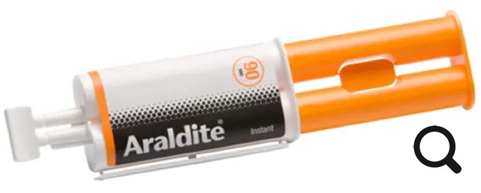
- Epoxy glue (Araldite 90 for example)

- Gear puller

- 1.4 mm pin for gear puller

- General model making tools


Installation time: Around 1 hour

Unsure if it fits your model? Just reach out!

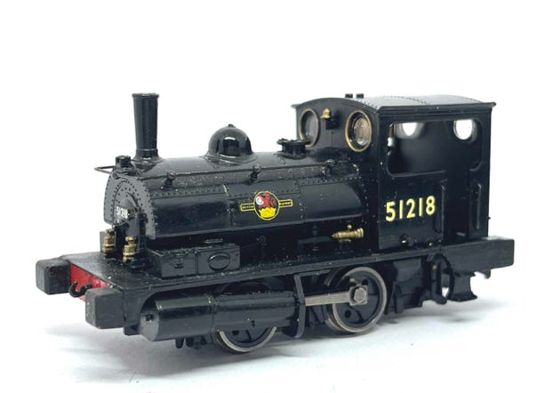
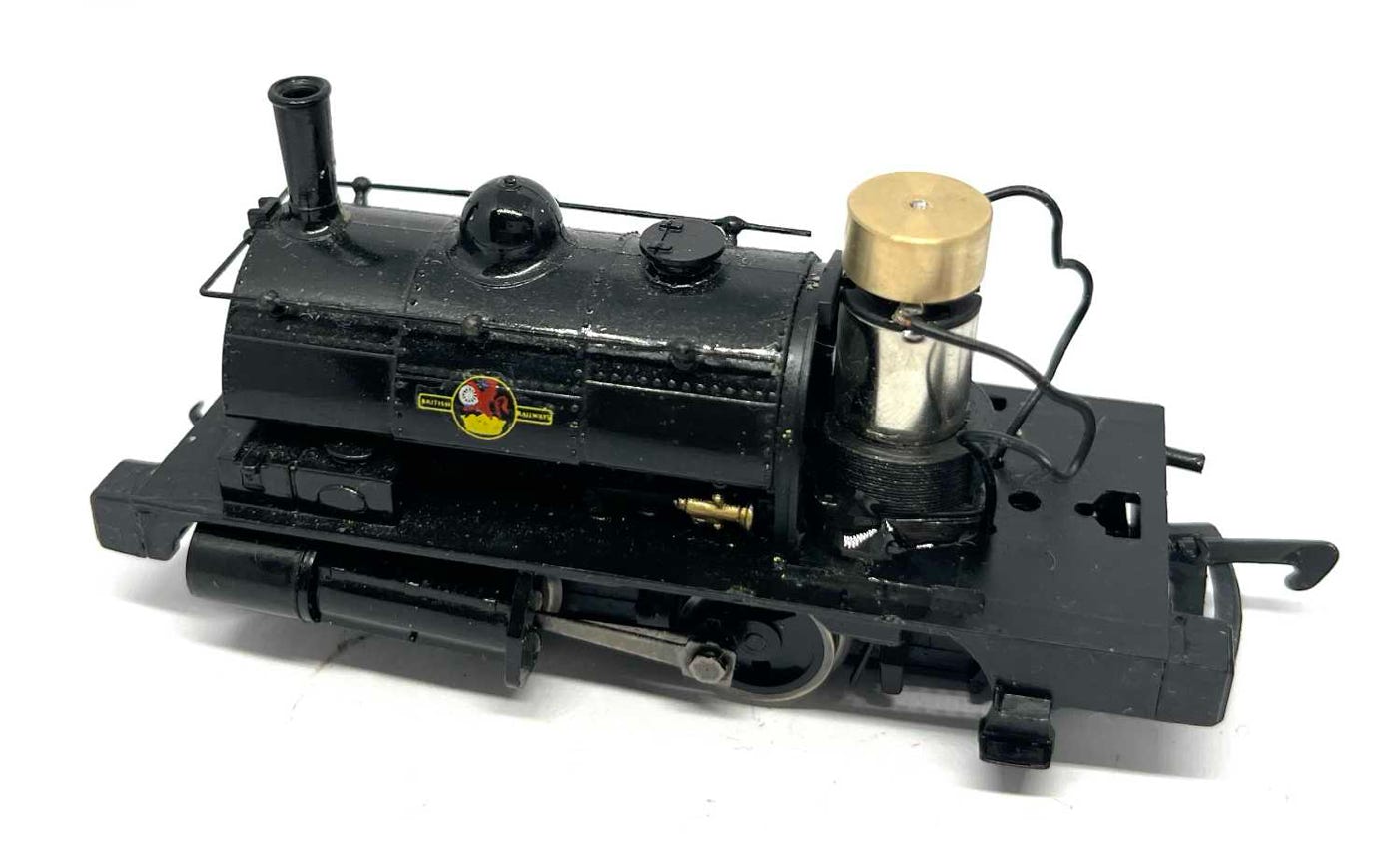
Upgrade for Hornby Pug

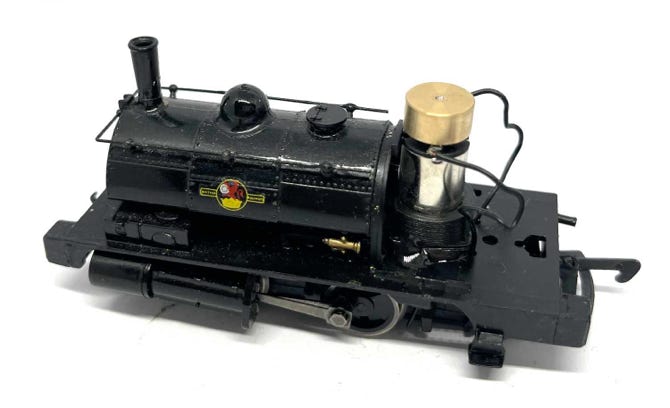
12V coreless Motor Upgrade

Why replace the motor with this coreless motor, when the original motor is not that bad?

√ Quieter

√ Earlier start at lower voltage

√ Takes up less space

√ Replace broken motor

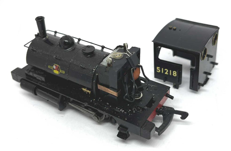
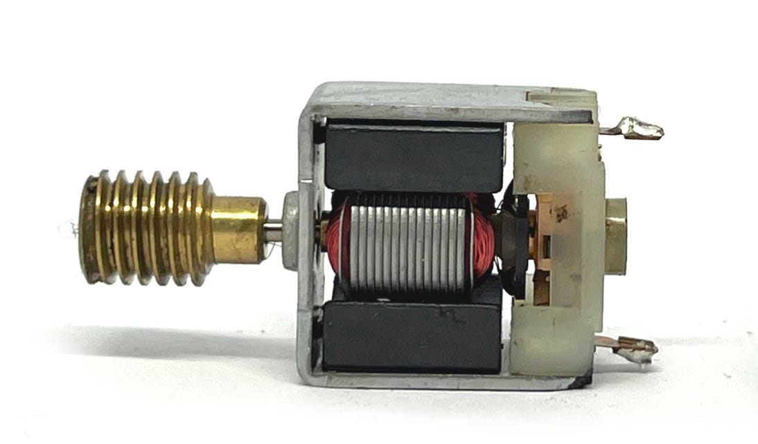
Original motor

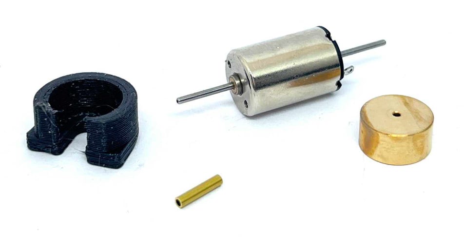
Contents of the kit (flywheel optional)

Instructions

1

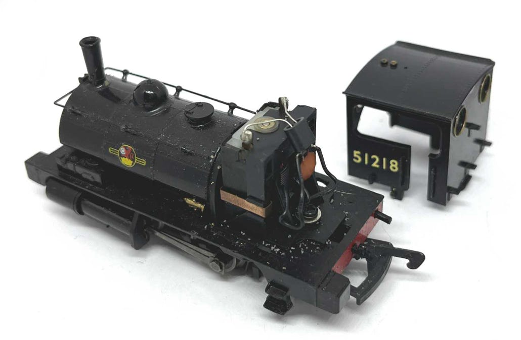
The cabine is connected with three tabs. Squeeze the sides to pull the cabine off the footplate.

Separating the driver’s cabine  from the chassis.

2

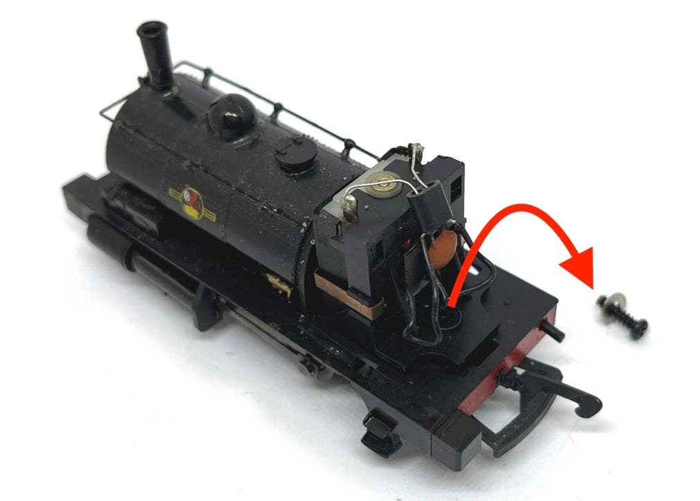
Remove the screw that holds the motor in place. You don’t need that screw anymore.

3

Desolder the wires from the motor. The only thing we need from the motor is the worm. 

You can put the capacitor that is connected to the motor to the side. This is to avoid FM radio disturbances. I don’t fit this back, personally.

4

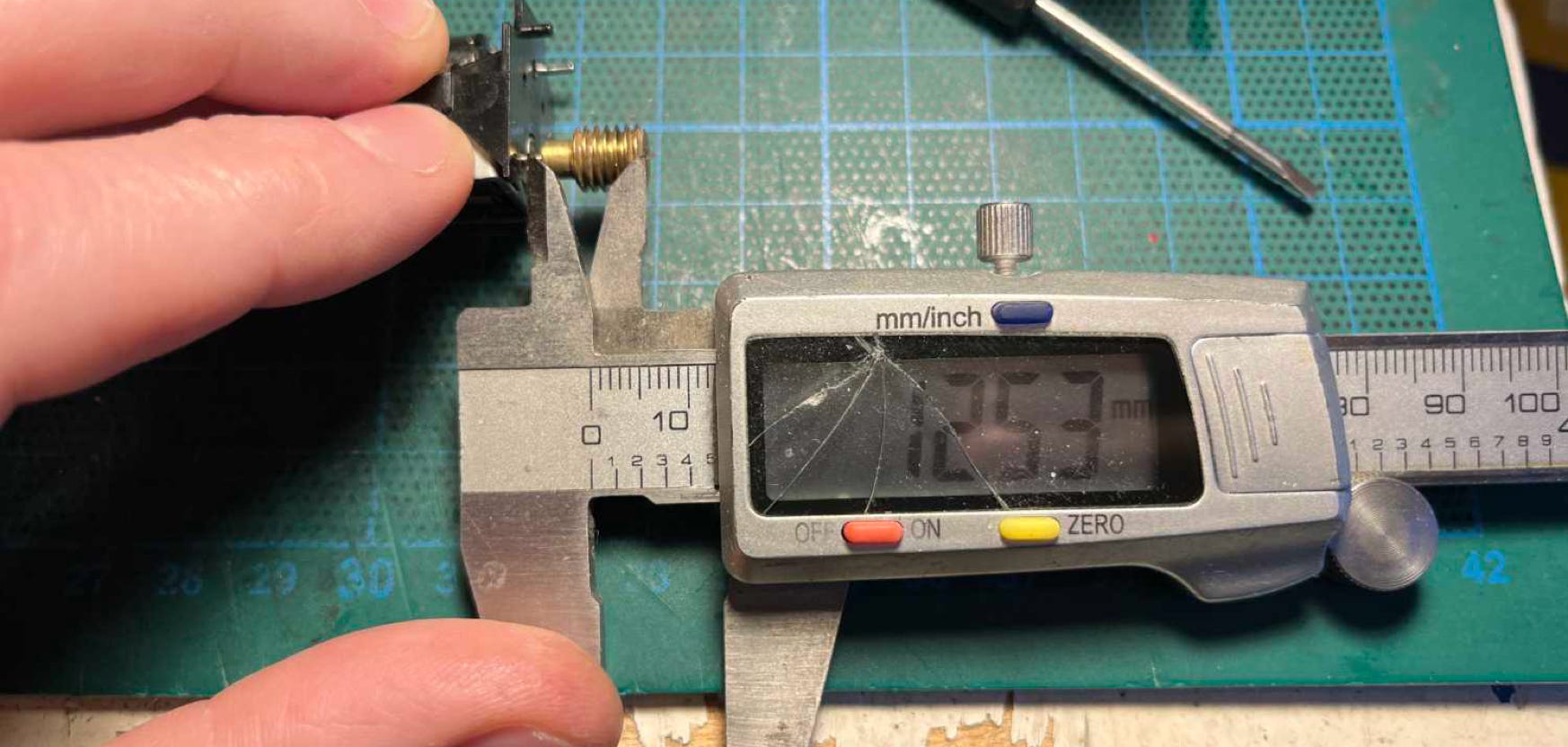
The end of the worm is fitted 12.5 mm away from the bottom of the motor plate. Take note of this when fitting the worm on the replacement motor.

5

6

7

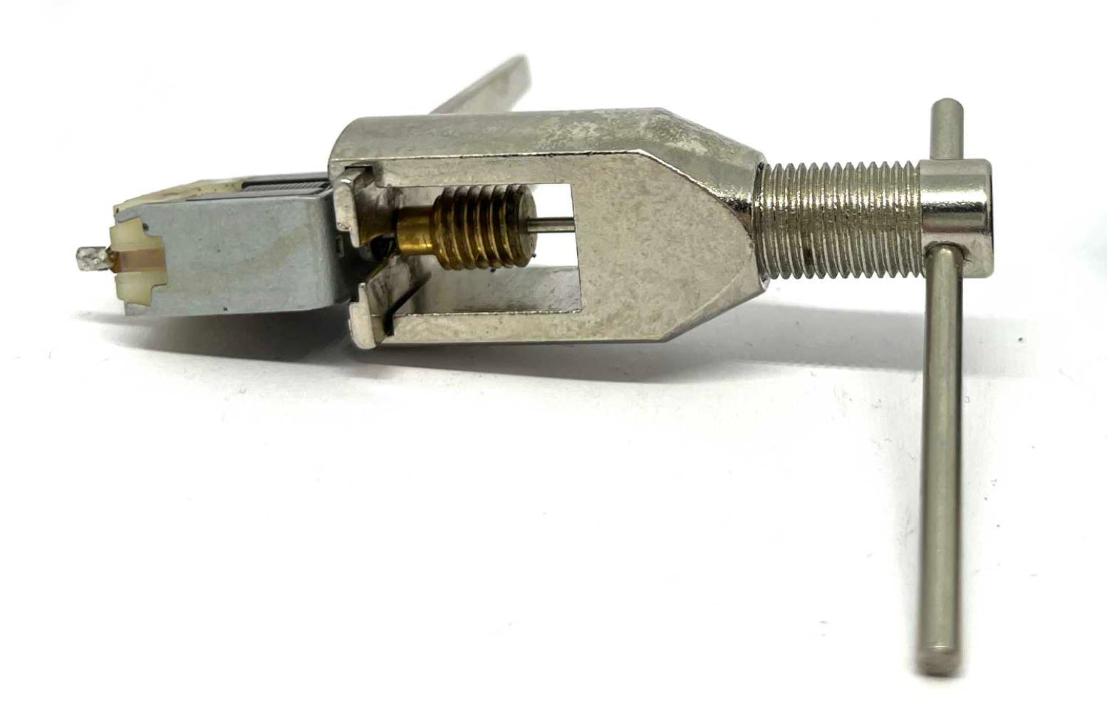
Using a Tramfabriek Gear Puller and the additional 1.4 mm pin, remove the worm from the original motor. This will be firm, but easy. Everything is easy with the right tools.

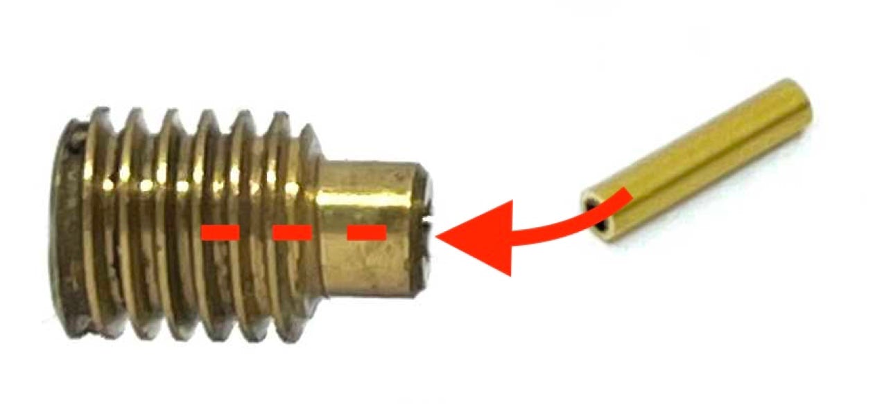
Press the 7 mm brass tube that comes with the kit in the smaller end of the worm. You can completely press it in, until the ends (at the narrow side of the worm) are aligned.

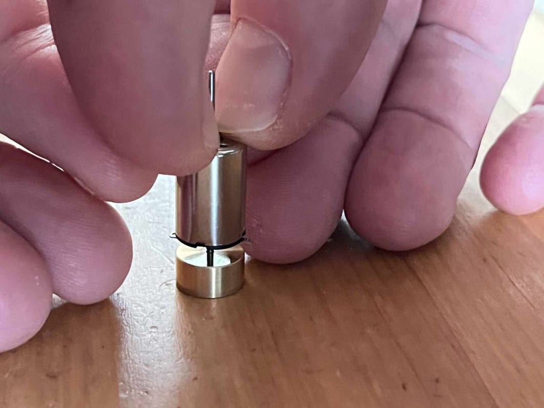
If you’ve optioned for the flywheel, press the flywheel on the motor shaft (contact side). Leave enough room so the flywheel doesn’t touch the contacts and you are still be able to solder the pickup wires to it.

8

10

9

-

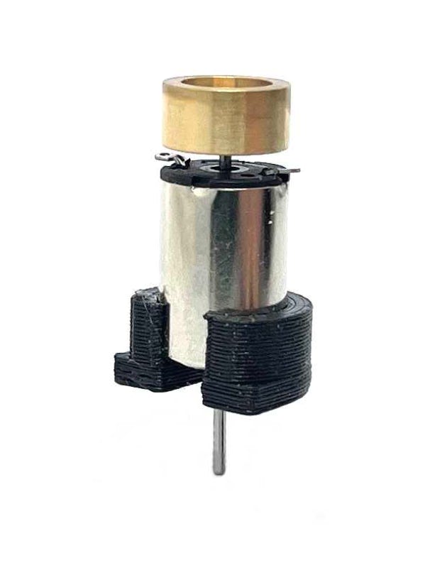
Press the motor into the plastic holder. You should not need glue to keep it in place. Check the polarity of the contacts. If you connect the wires the wrong way around, the train will run in opposite direction of all your other trains. But easy fix, just swap the cables.

+

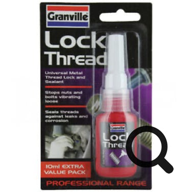
Fit the worm on the motor shaft. To keep it from moving, you might need a drop of Lock thread (the blue metal glue). Remember that the end of the worm should be 12.5 mm away from the bottom of the plastic motor holder.

With sand paper, degrease the footplate. Then, with three dots on each (bottom) side of the casing with epoxy glue (just small drops will do), glue the assembly on the footplate. 


Make sure you keep the motor assembly centred and press it against the boiler, to align it correctly. I always use Araldite 90 seconds drying time glue.

11

Solder the wires. If you want to convert to DCC, first test if it runs well in analog. If you need to re-align the motor, it’s quite easy to remove it if you want and start over again.

Test the drive and when it’s all right, reassemble the model and enjoy the improved running capabilities!

END