

UK based
Prices for UK customers are shown inc 20% VAT
Other countries, inc EU, prices shown are ex VAT.

KASTENLOK INDEX

1
2
What you need for conversion set
- The model and upgrade kit
- Small screwdrivers
- Soldering iron 15W/25W
- General model making tools
Installation time: Around 40 minutes
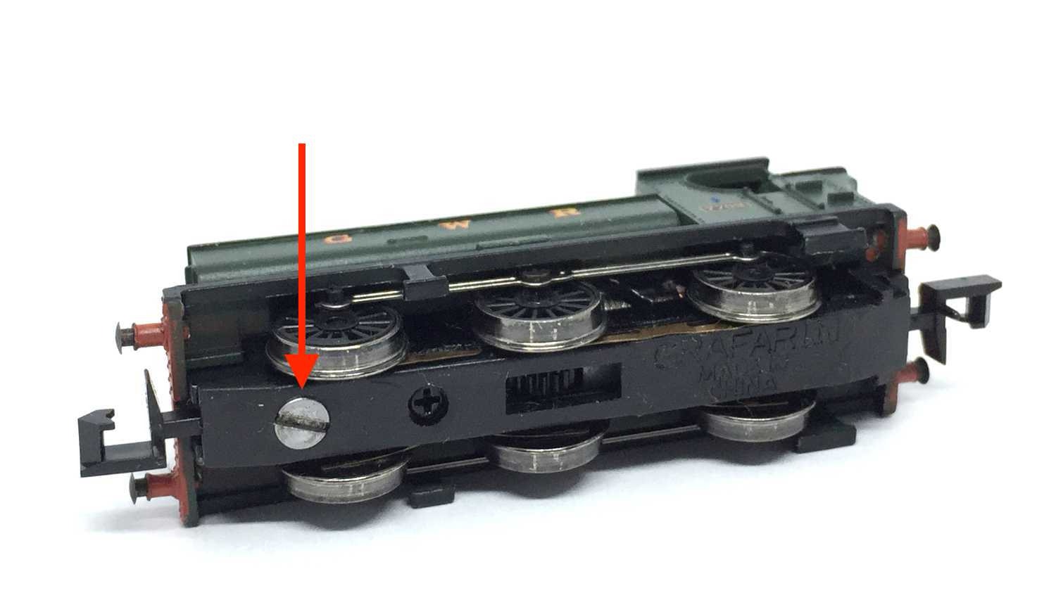
Take apart
Remove the screw under the chimney and lift the housing off the chassis.
Remove the bolt on the top and keep it aside. You need this later again. The screw attached to this bold is the contact point to the power pickups from the right wheels (seen in the direction of forwards driving).
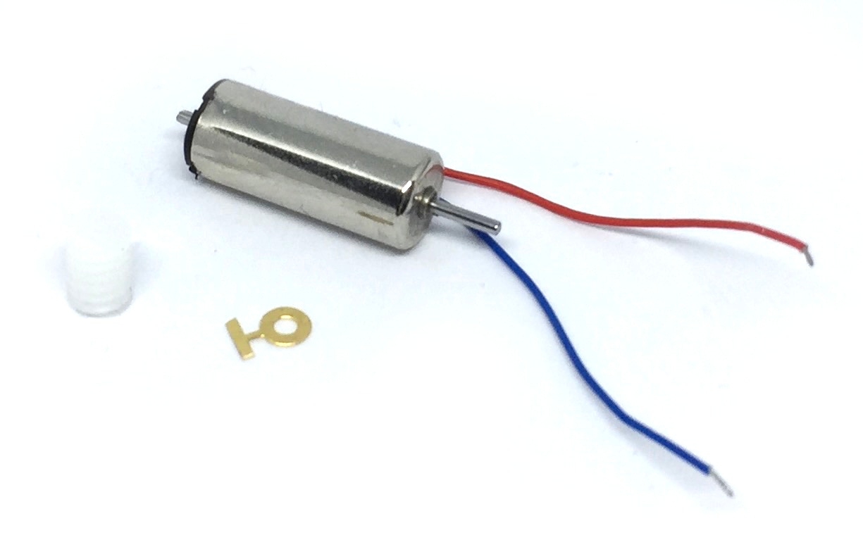
to 12V coreless motor
Fits on many, many other Graham Farish models with a similar motor design. If you are going to try this on your own, not listed model, be aware that there is one alternative upgrade. That one is for more commonly seen chassis. The only difference between the kits is the size of the worm. If you are in doubt, get the GF Standard upgrade kit and purchase the Tramfabriek part TFWOR3 with it, so you have both worms.
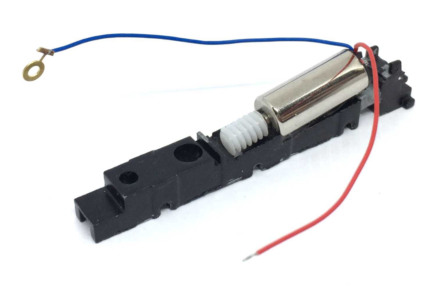
Contents of the kit.
3
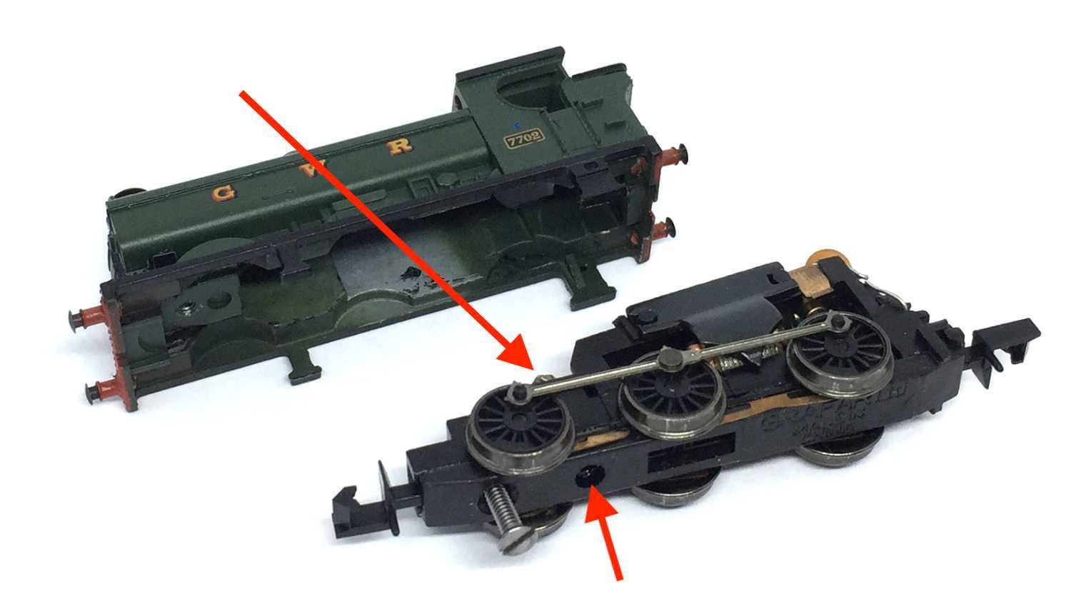
Remove the bottom plate, which is hooked to the chassis at the rear.
4
5
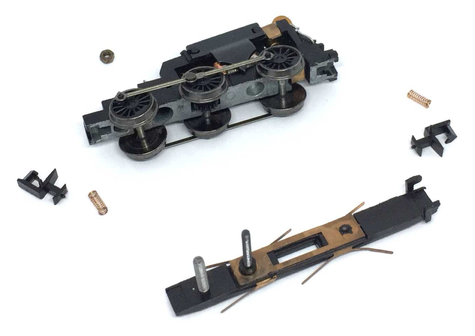
Take the wheels out. Inspect the gear for split. You need to look with a magnifying glass or make a sharp picture and zoom in, in order to check if there is a crack. This is quite a common problem. A 16 teeth replacement gear can be gotten from Graham Farish
Take the wheels out.
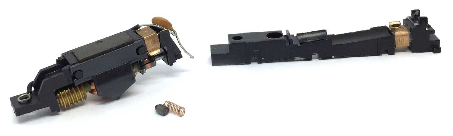
6
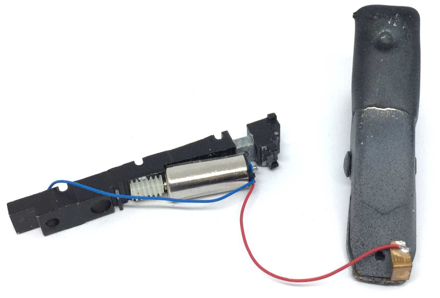
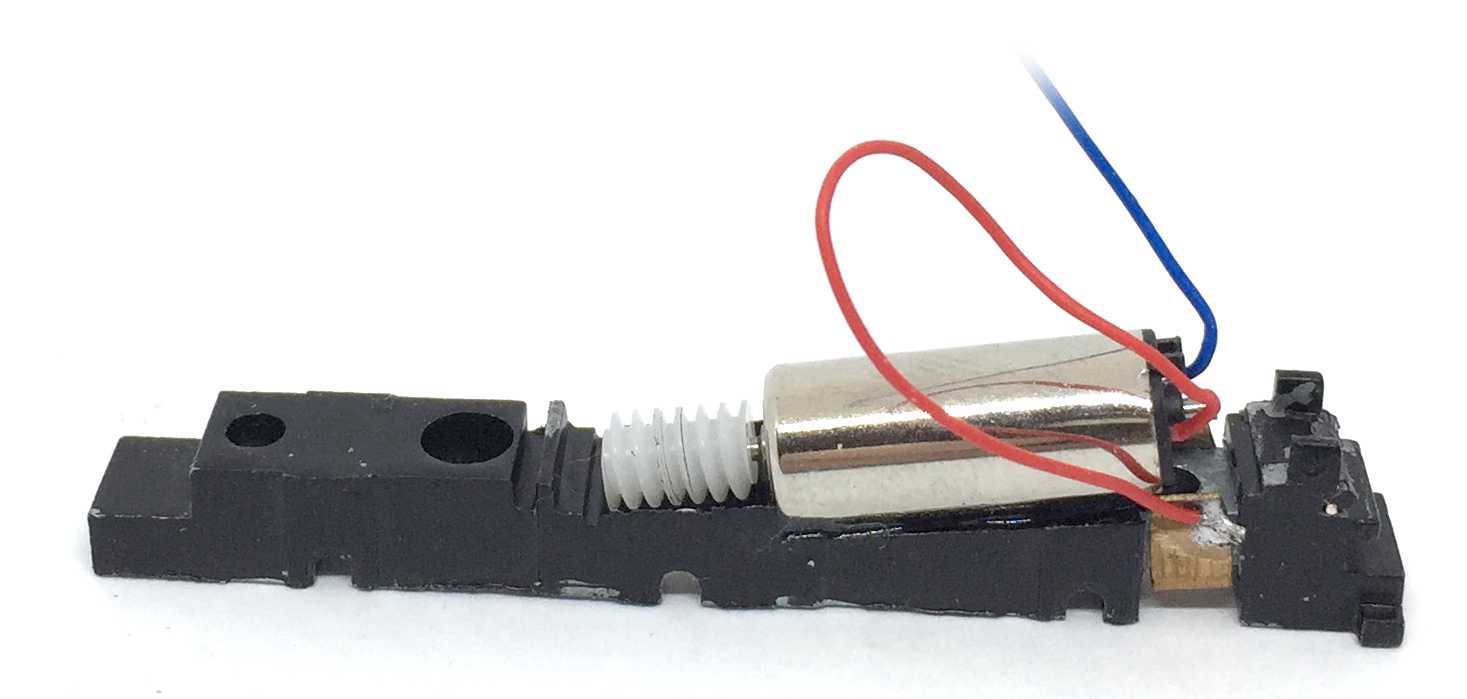
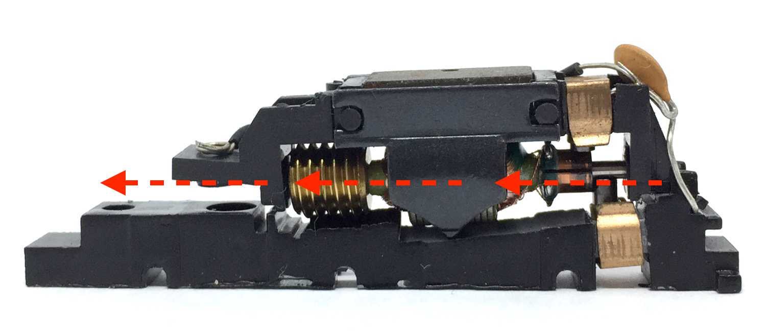
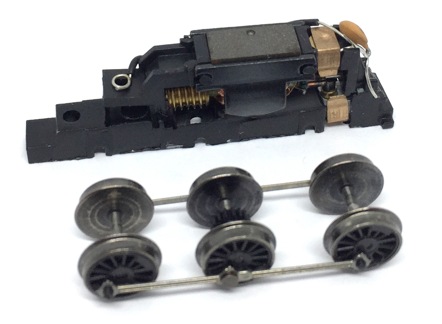
Slide the motor assembly from the model, in the direction of the arrows. You need to cut off the wire at the rear end of the model to completely remove the parts.
7
8
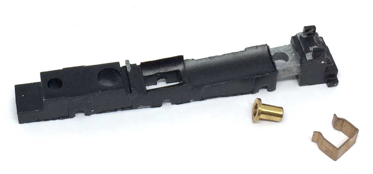
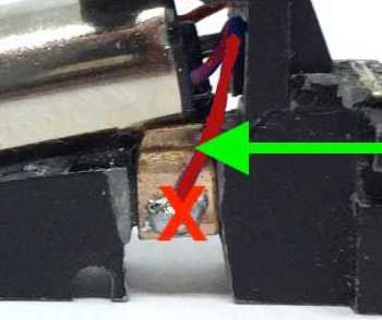
Continue with the bare frame. Remove the clip and bush. You don’t need the bush anymore, but the clip will be re-used.
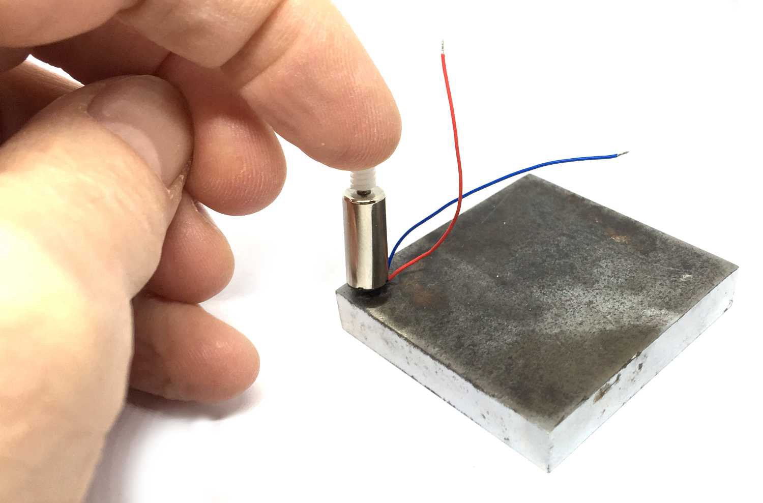
The motor will fit between the dotted lines. The motor will lean at the front against the raised part and at the rear just on the bare metal part.
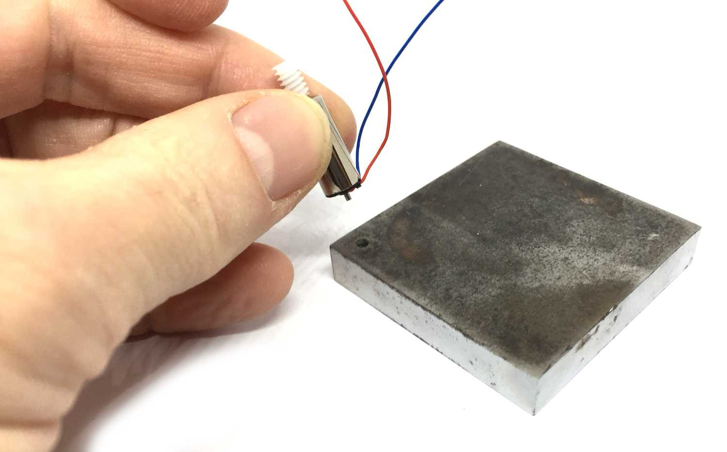
9
Fitting the worm on the motor shaft: No glue is needed, this is a press fit. Find a piece of wood of metal with a small hole in it. Note that the worm has a larger side on one side than on the other side. Press the side with the large hole a bit on the motor shaft. To completely press it on, put the motor with the rear shaft in the hole on the plate. Then press the worm on until it is almost touching the motor housing. If you press it on and not support the back, you will press the back out of the housing. The plastic back part is not glued.

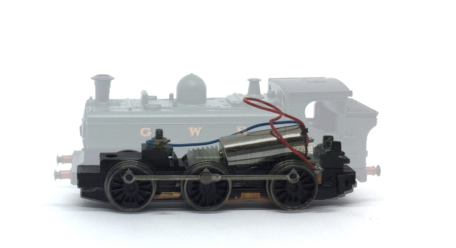
Graham Farish Pannier
(Also 4F, Battle of Britain & others)
Among others, also compatible with:
Pannier, 4F, Battle of Britain
Question? Just reach out!
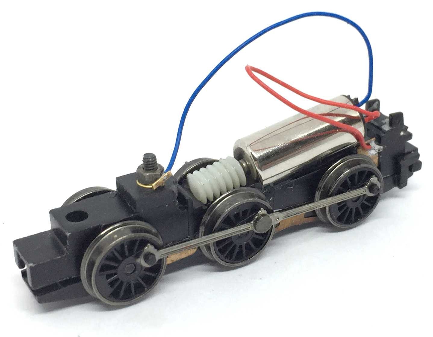
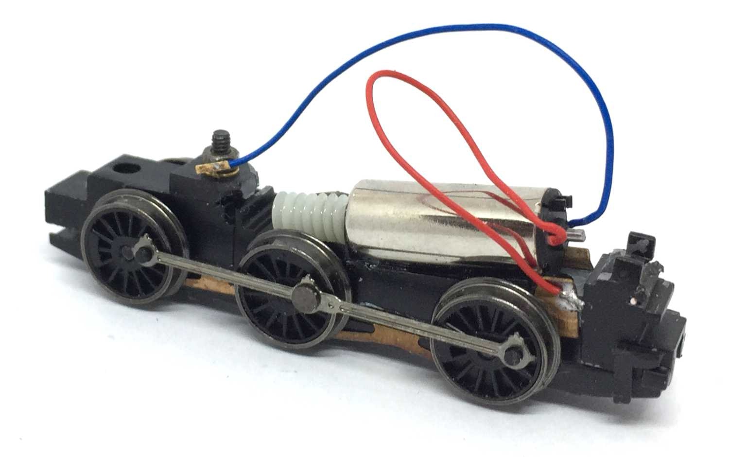
This is the result