

UK based
Prices for UK customers are shown inc 20% VAT
Other countries, inc EU, prices shown are ex VAT.


UK based
Prices for UK customers are shown inc 20% VAT
Other countries, inc EU, prices shown are ex VAT.
Compatible with (among others):
3F Jinty, Large Prairie, A4,
Black 5, 8F, Merchant Navy,
94xx
Graham Farish Large Prairie (& others)
to 12V coreless motor
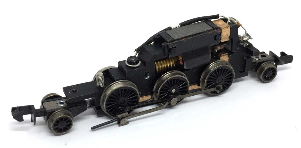
Before
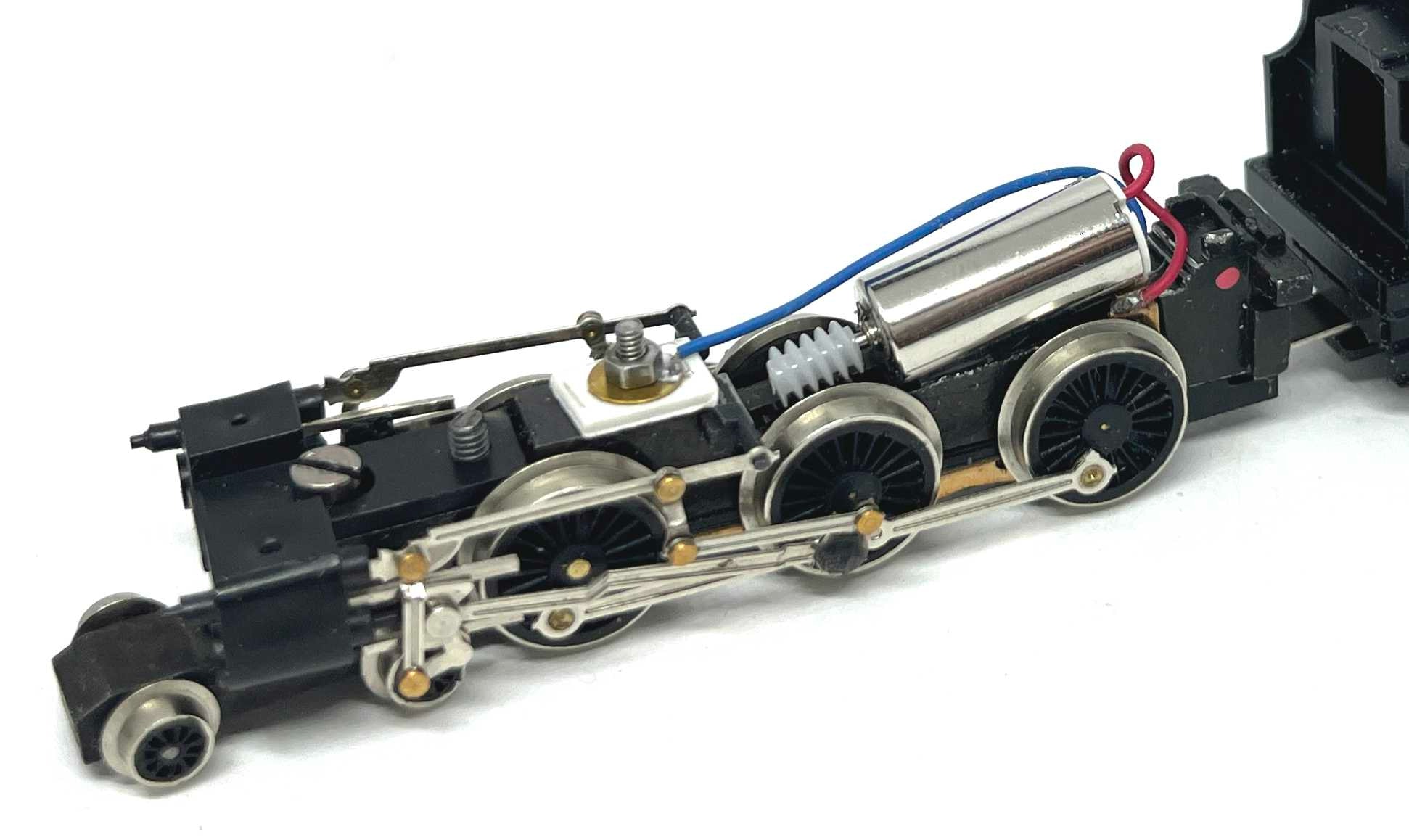
After
What you need for conversion set
- The model and upgrade kit
- Small screwdrivers
- Soldering iron 15W/25W
- General model making tools
Installation time: Around 60 minutes
Fits on many, many other Graham Farish models with a similar motor design. If you are going to try this on your own, not listed model, be aware that there is one alternative upgrade. The only difference between the kits is the size of the worm. If you are in doubt, get the upgrade kit from this page and purchase the Tramfabriek part TFWOR3 (larger worm) with it, so you have both worms.
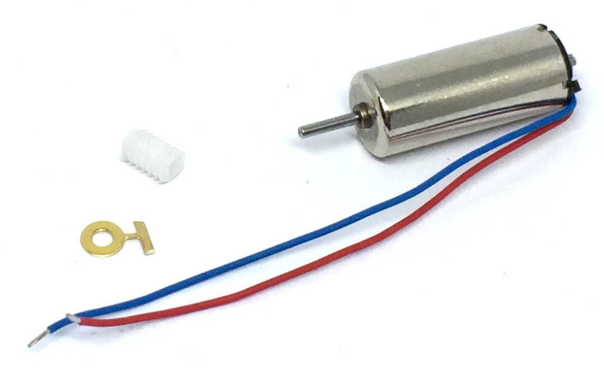
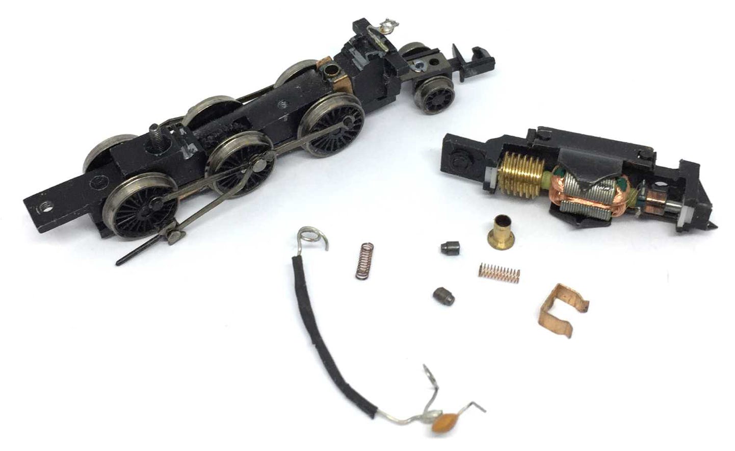
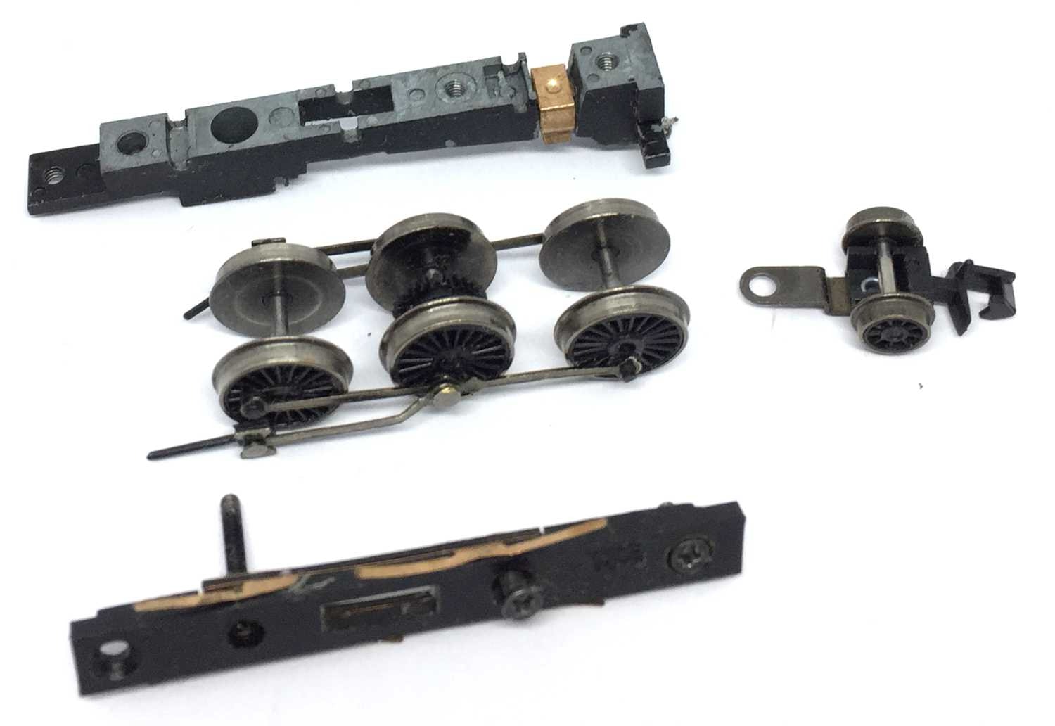
Contents of the kit.
Question? Just reach out!
1
2
4
Take apart
Remove the screw under the chimney and lift the housing off the chassis.
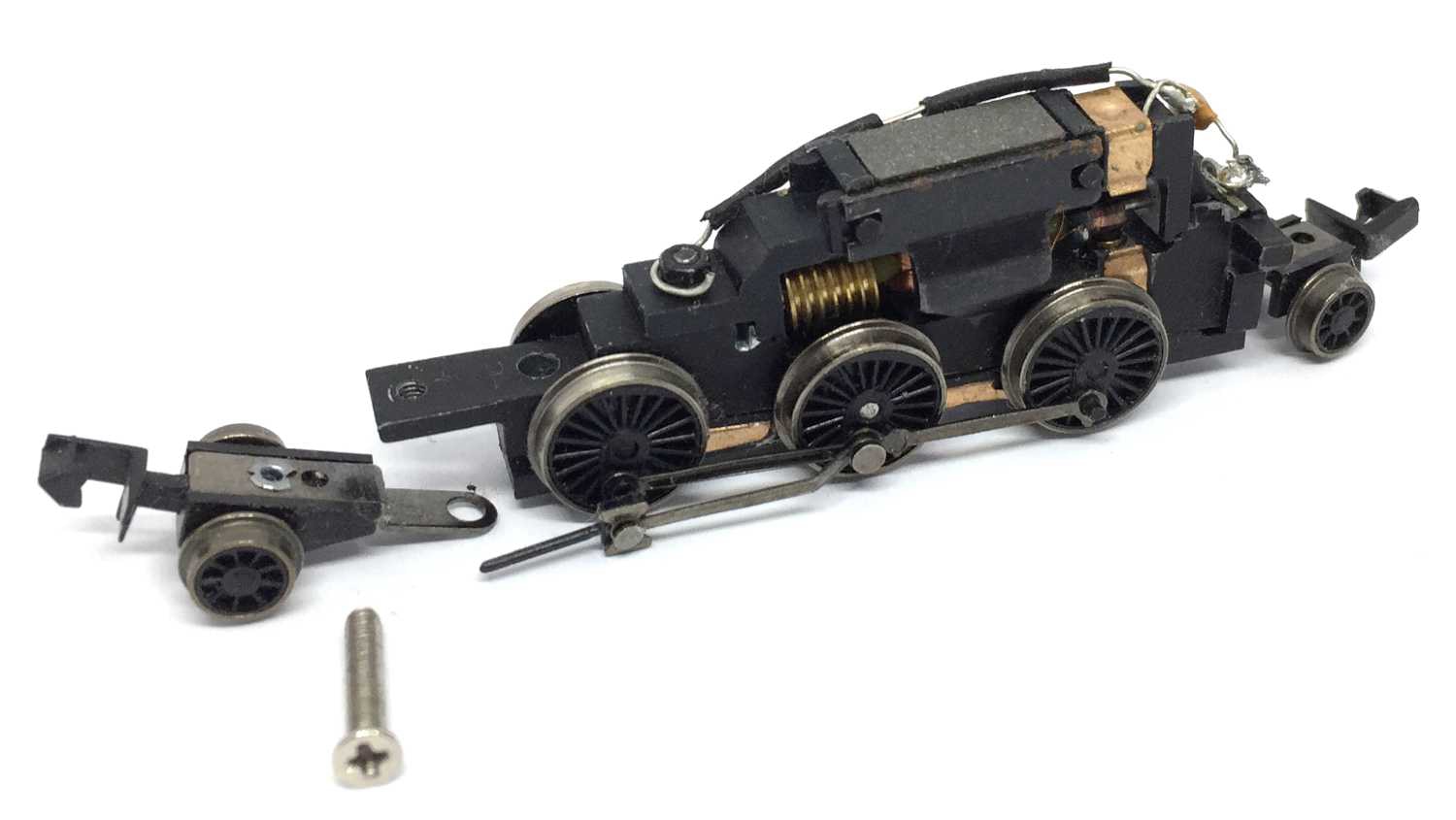
You can take the smaller wheels off, on both front and back.
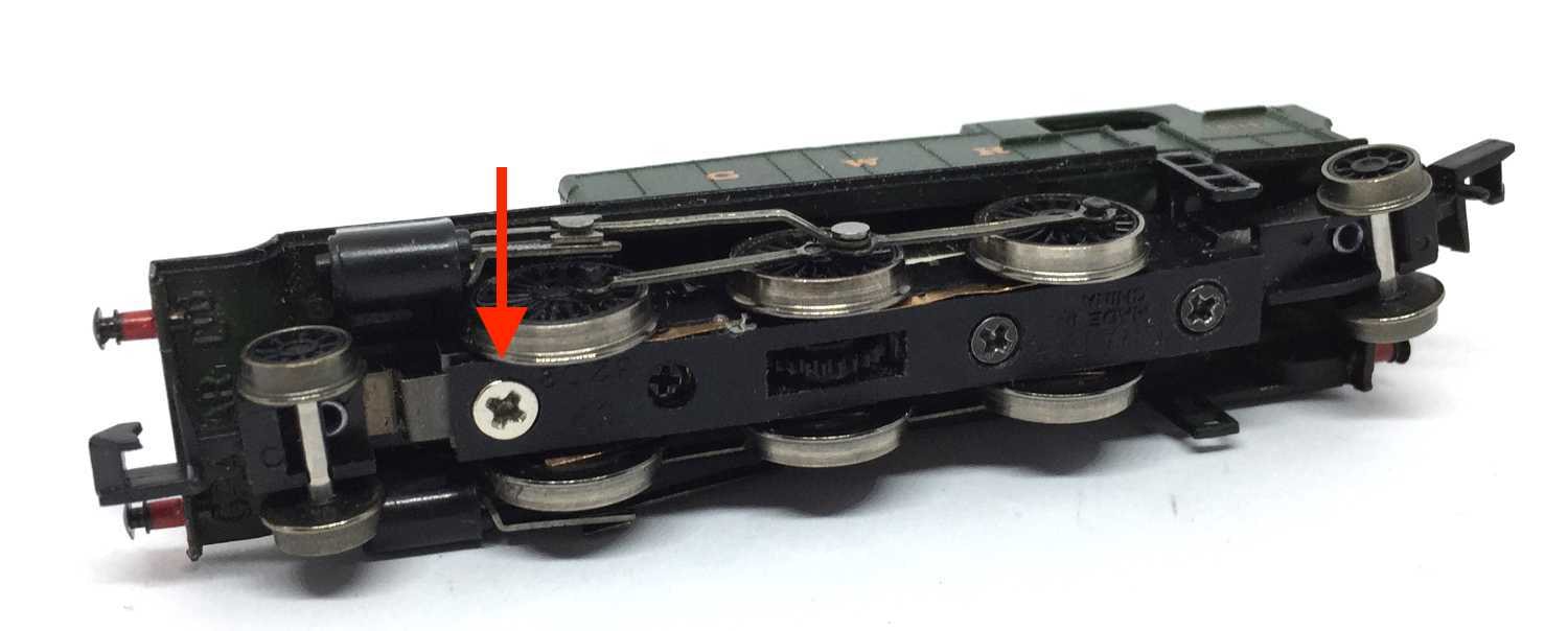
3
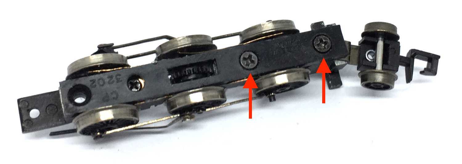
Remove the bolt and keep it aside. You need this later again. This screw is the contact point to the power pickups from the right side (seen in the direction of forwards driving).
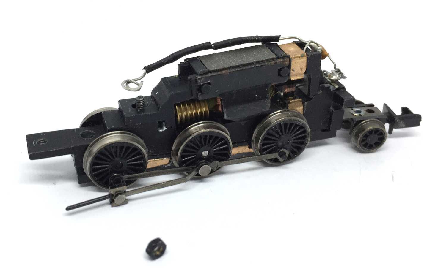
Take all these parts out. You only need the cover of the motor. You need to cut off the wire at the rear end of the model.
5
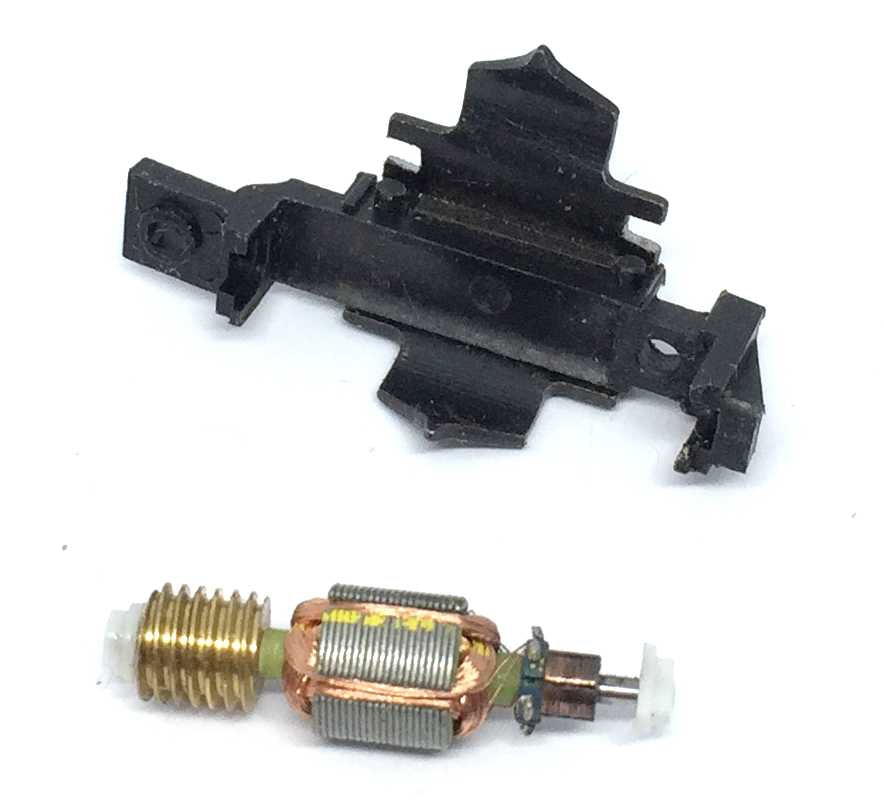
Remove all parts that surround the black plastic cover, including metal plates and magnet. You only need the large plastic cover.
!!!Please note that the rear part of the motor cover slides to the front! Don’t pull it upwards, but slide it out forwards!!!
If this is unclear, see step 13.
6
Remove the screws that hold the bottom plate in place. This might be different with your model.
7
Result.
8
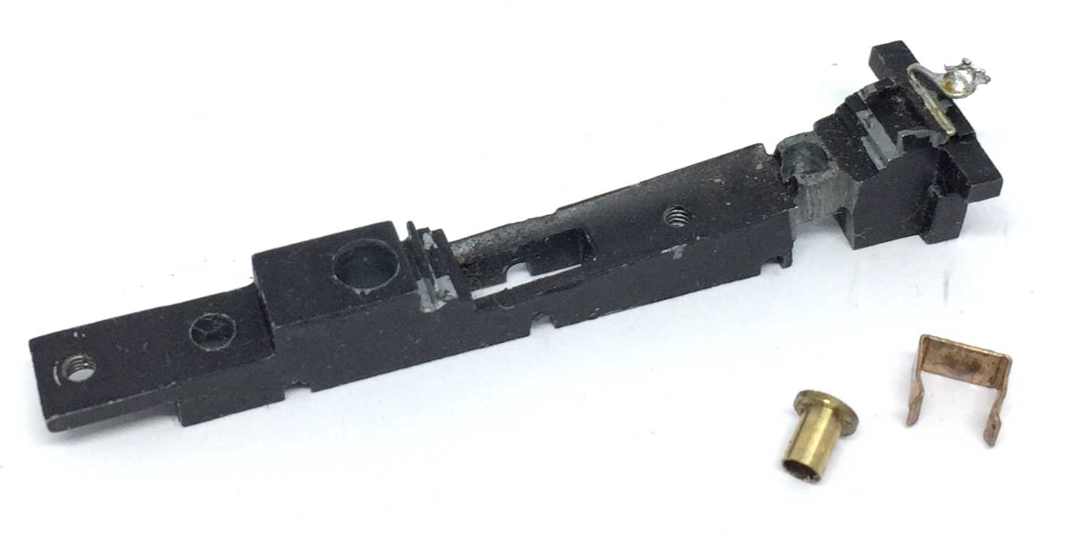
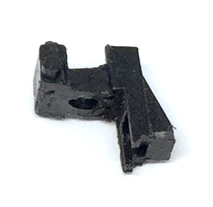
Take the brass hat and clip out. You’ll need the clip again in a next step.
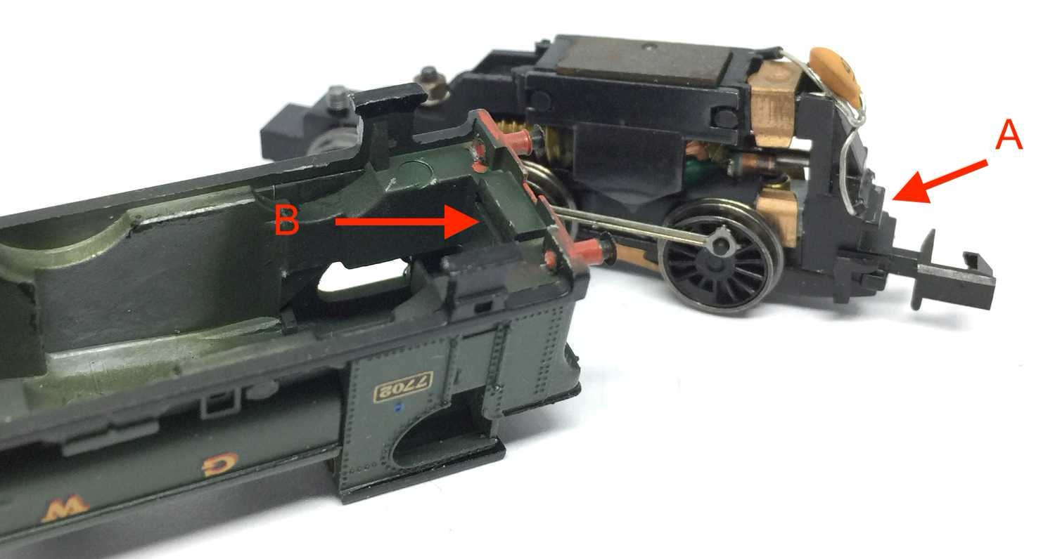
9
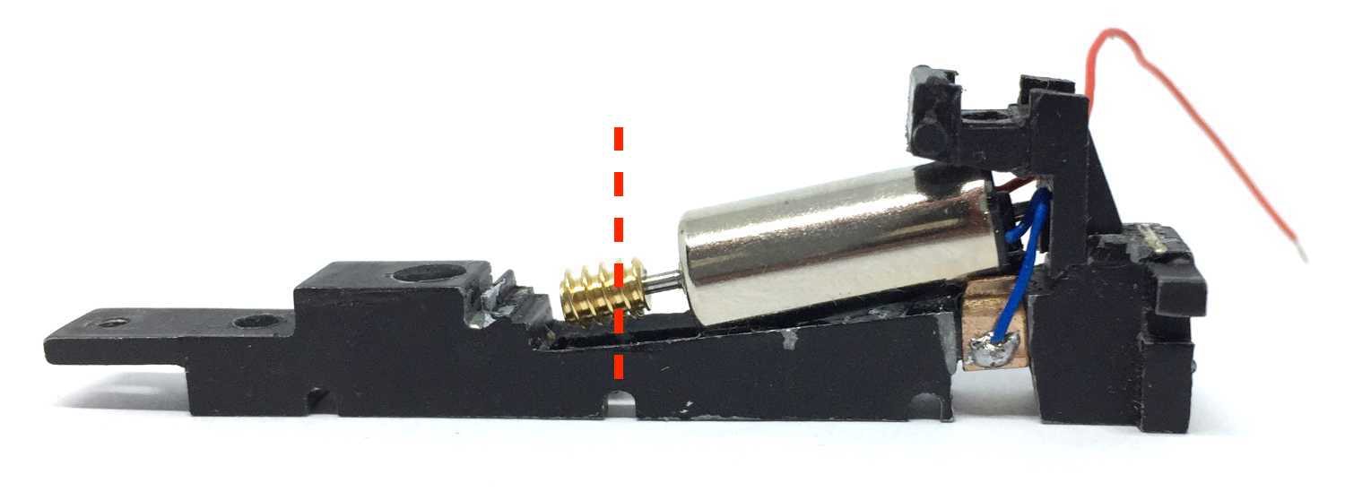
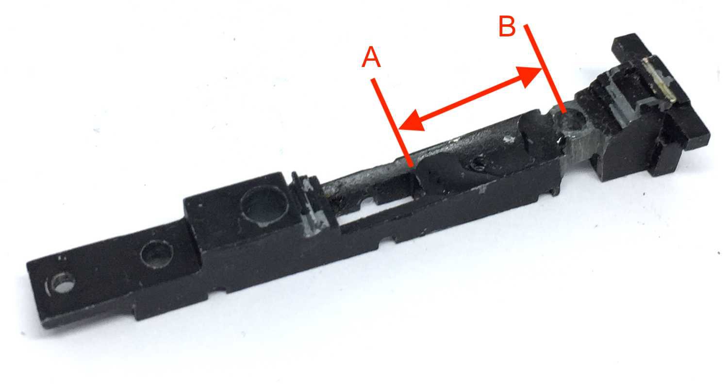
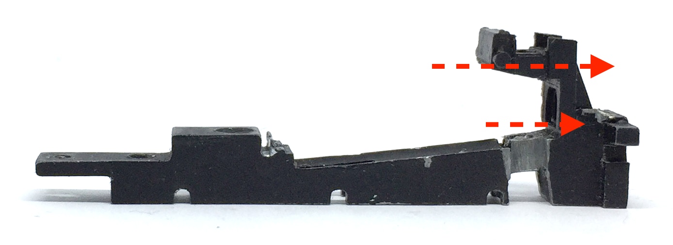
The motor will fit between A (where the gear hole ends) and B (just on the start of the screw hole).
10
Before you continue, please take note: it has come to my attention that some motors seem to be wired differently, which means the electrical poles of the motor are swapped. This means the red wire should lead to the front of the train, while the blue wire has to go to the clip. So test if the direction of the model is going in the same way as your other models. If not, swap the wires around.
Don’t pay attention to anything else but the the placement of the worm. Align the centre of the worm with the centre of the axle hole. Using Loctite or Granville Lock thread (any liquid metal glue will do), glue the brass adapter in the gear. Don’t fit the brass adapter on the motor shaft first, but the adapter in the worm. After a minute of drying, you can fit the worm on the motor shaft.
If it is a tight fit, you don’t even need to glue the worm.
!
IMPORTANT NOTE: The cutting up and re-use of the plastic motor cover, explained in the following steps (11-16), is probably unnecessary. Later I found that the second hand model I was working on was most likely missing a part in the back, that holds the rear of the chassis in place, so the motor cover functioned has an aligner for the housing. It is very likely that all models have a construction in the back that hook (A) into B, so you can just leave out the plastic motor cover completely. I also saw another construction, so it doesn’t have to look like this.
!
11
12
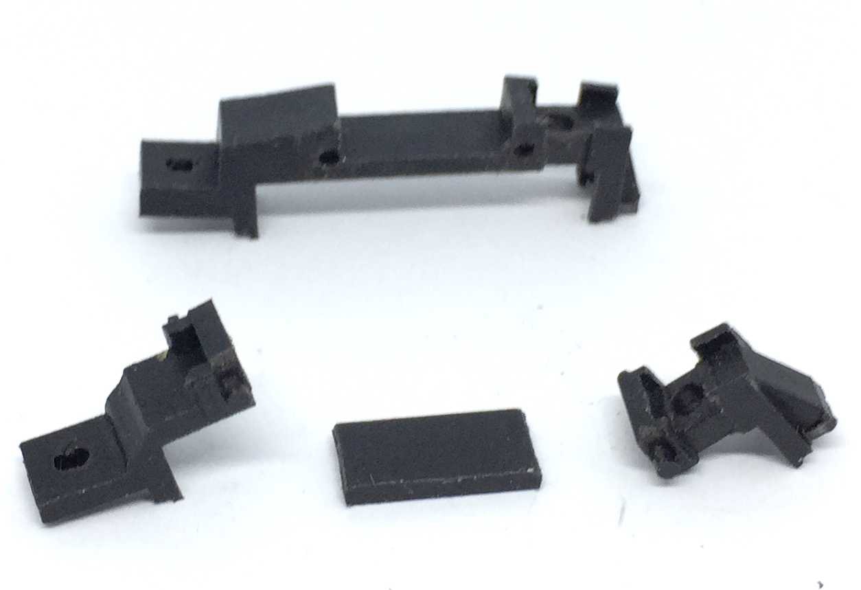
Cut the plastic motor cover in three pieces. We don’t need the middle part anymore.
We continue with the rear part of the motor cover, pictured at the extreme right above. With a sharp hobby knife, cut a triangle as indicated. This needs to be done, otherwise there is no space enough for the motor. We need to install this part, as on many models, it keeps the correct height of the housing. See next step for exceptions.
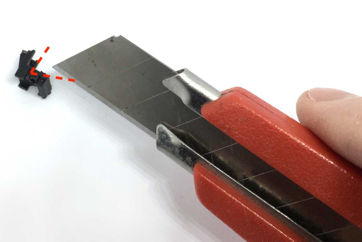
Result (enlarged):
13
Slide the rear motor cover part back into place.
14

15
17
18
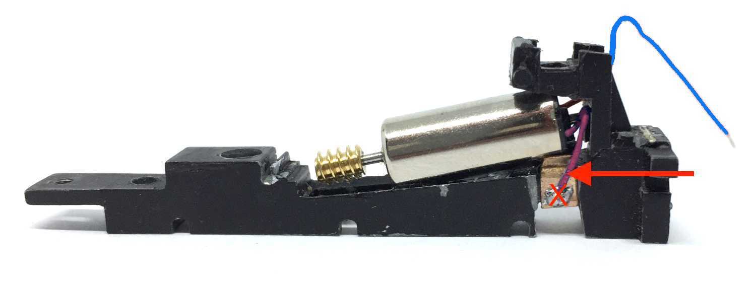
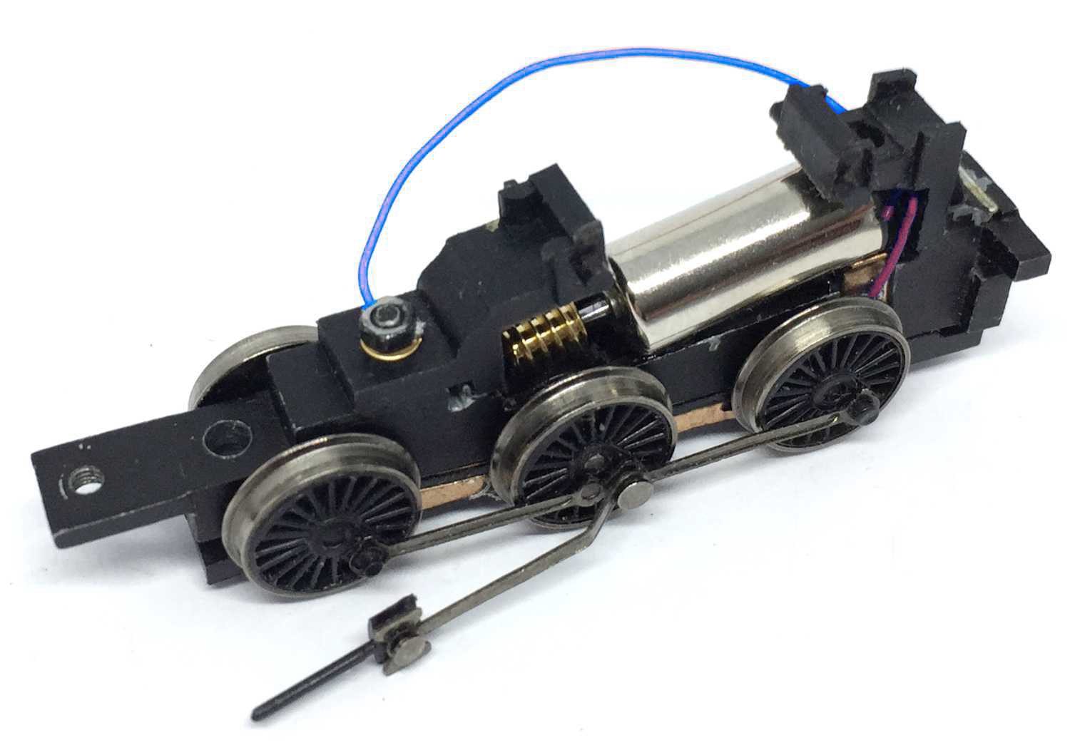
Make the space to glue the motor grease/oil free. Then, using 90 seconds Epoxy glue, glue the motor in place. Lead the RED wire to the LEFT, the BLUE wire to the RIGHT. Read next step before soldering the wires.
Soldering time! If you are not going to run this model DCC, then you can keep the red wire pretty short. Using the clip, solder the red wire to it. Do not solder it so low as I’ve done here, as then it will touch the wheel and create a short. It has to go where the arrow is pointing to.
16
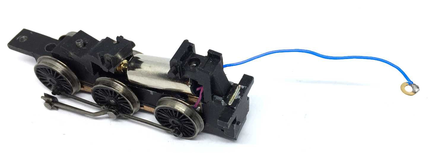
Solder the blue wire to the brass ring, supplied with the kit.
Place the wheels and bottom cover. Fit the front part of the motor cover. The wire with the ring go on the screw and fix it with the bolt.
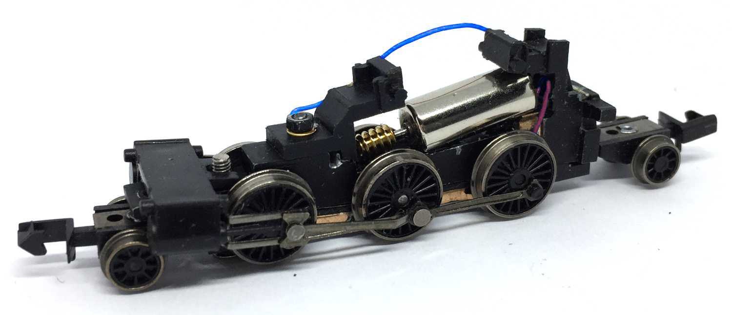
Test it and when all is working fine, re-assemble the model. Getting the gearing back in the cylinders is quite fiddly. You know, you get one side in, then when you are fitting the other side, the first one gets out again…
Then you’re done. Unless you want to make it digital…
Digital conversion
If you want to make it digital, the Train-O-Matic Micro decoder fits on top of the motor. Available from the Tramfabriek here. The perfect CV settings for this motor for several decoder brands you can find by clicking here.
•