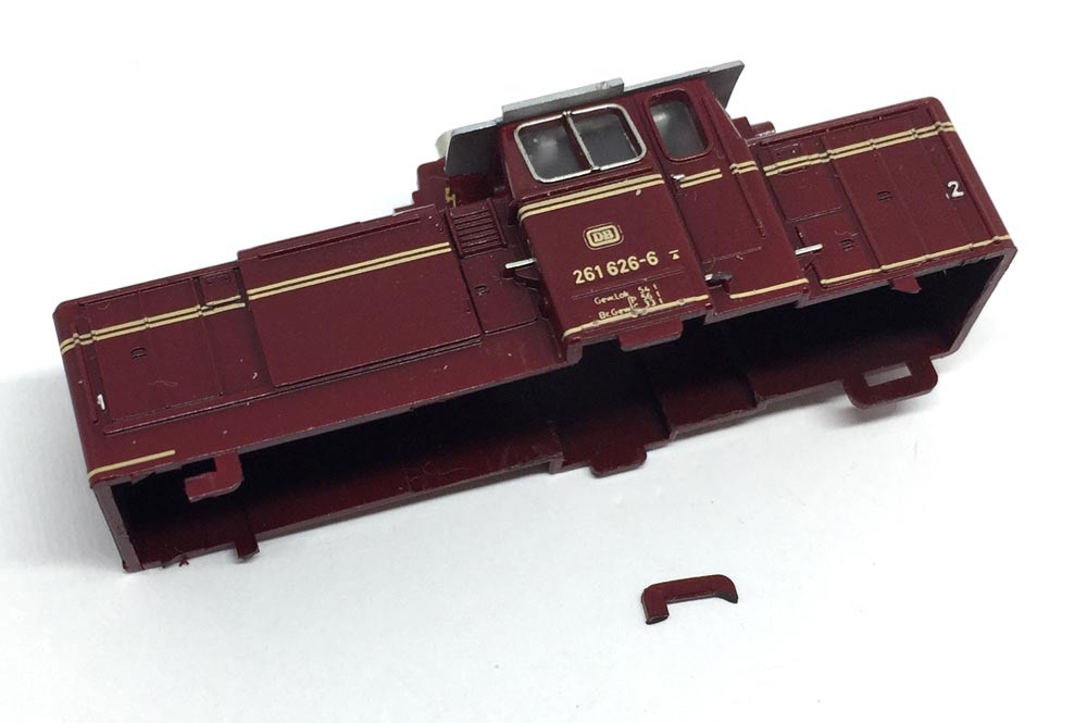
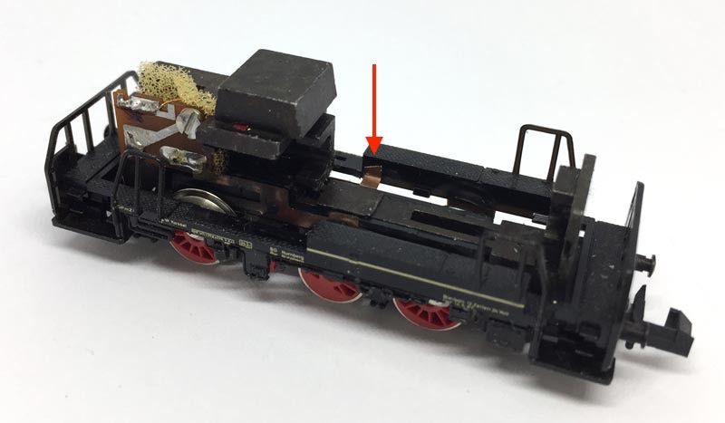
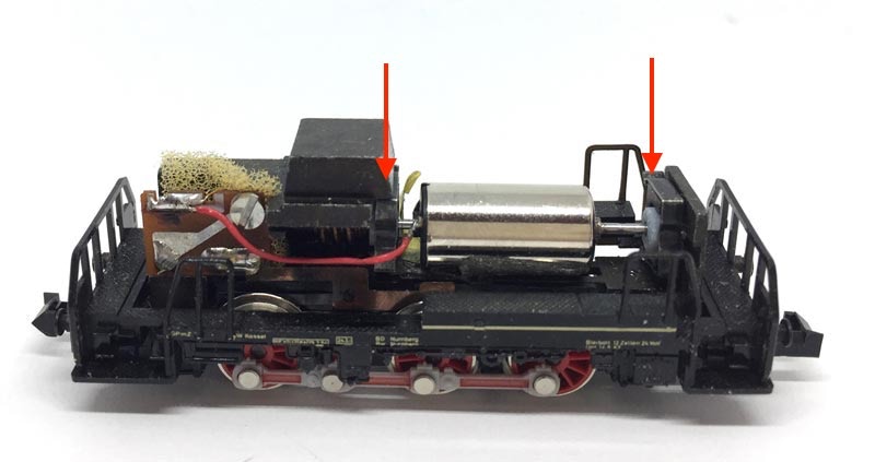
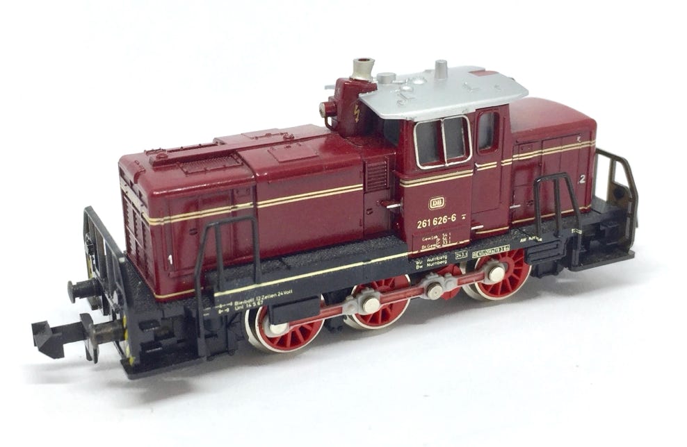
Upgrade Minitrix V60

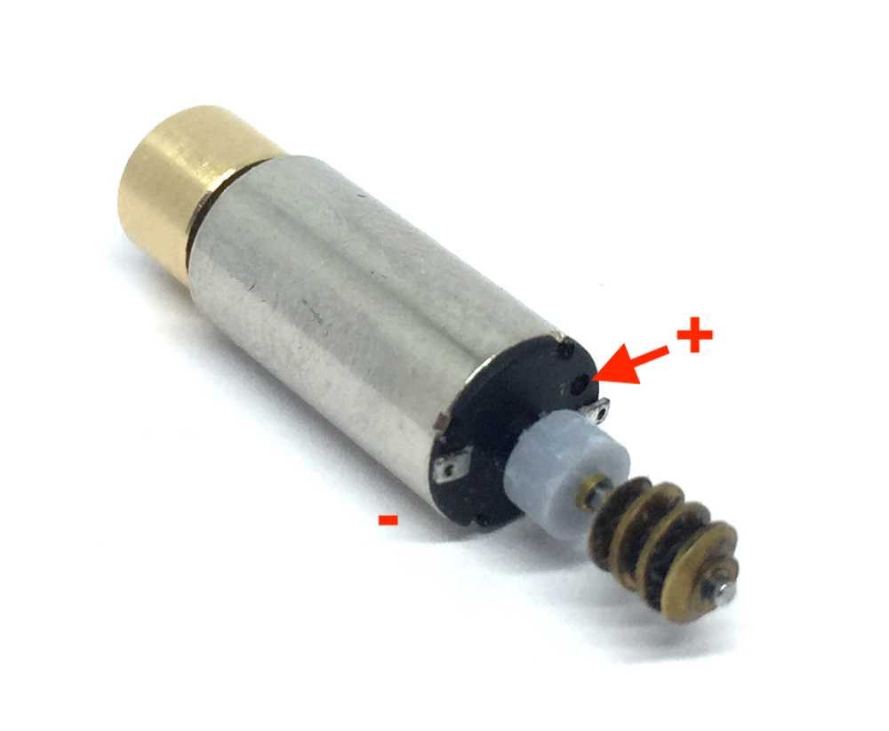
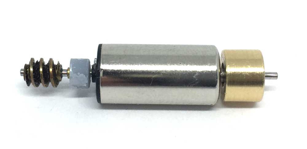
to 12V coreless motor

Fits all Minitrix art. 51 2064 00, 12064, 12098, 12842, 12844, 12848, 71000, 11031

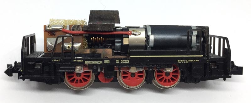
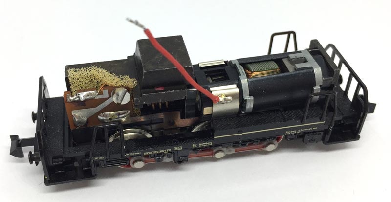
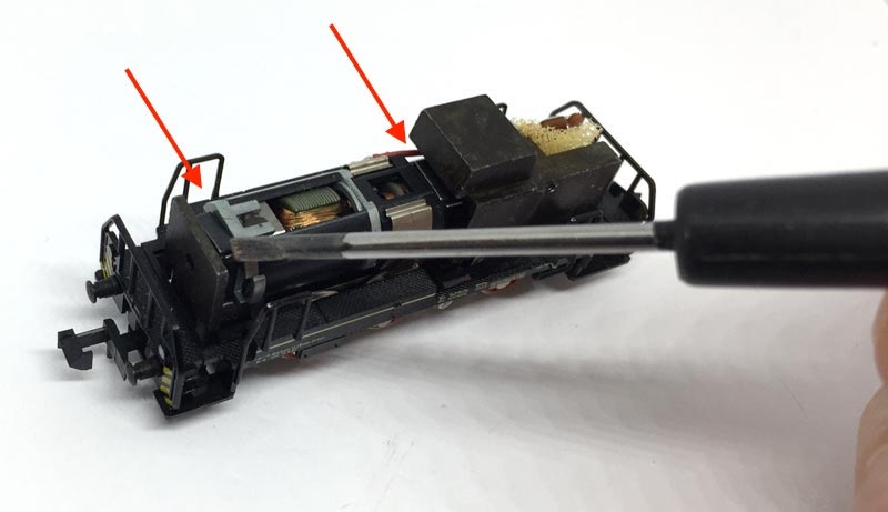
What you need for conversion set

- The model and upgrade kit

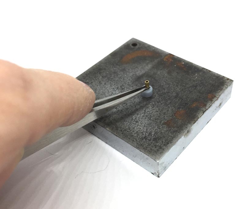
- Small flat screwdriver

- Soldering iron 15W/25W

- Something to cut


Installation time: Around 40 minutes

Difficulty: Bit fiddly, but easy
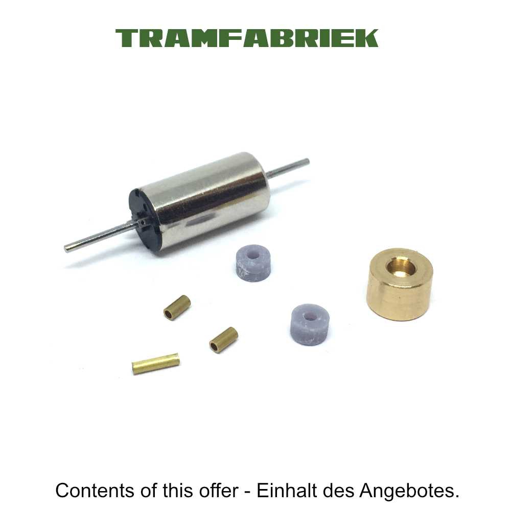
Brass worm now included!!

Contents of the kit

KASTENLOK INDEX

Question? Just reach out!

1

It’s not a very easy model to open. The hooks might be brittle, because of the age of the model. There are four (red) hooks on the housing, which are held by tabs on the black frame.

As you see, not everything worked out for me. I got annoyed. Oh well, it fitted perfectly afterwards.

2

4

This is what we are dealing with.

De-solder the red wire to the motor from the board.

3

Remove the two clips that hold the motor in place.

5

Kit with worm, continue below

Place new worm on the shaft of the coreless motor and check for correct alignment. Run the motor to test. If it is all running great, use metal glue like Loctite or Granville (ideally the blue lock thread version) to glue the worm in position.


(Earlier versions of the kit came without the worm, but with an adapter to fit a worm.)

5

Kit with brass adapter, continue below

Remove the worm from the original motor (do not use the Tramfabriek gear puller here, as most of the time, the worm is fitted too tight and you will break the pin. You’ll need to heat it up with a torch. For more valuable tips how to remove a worm, gear or flywheel, click here. If you find it difficult, you can order a worm from the Tramfabriek. Just contact me


Then press the brass adapter in the original worm. Be careful with the adapter, the wall is only 0.1 mm thick. You might have to clean out the worm to make room for the adapter.

6

Press the brass tubes in the two discs that came with the kit, if this isn’t already the case. A push with a flat screwdriver should be enough, otherwise with a small hammer.

7

Cut contact strip. Leave enough so you can solder the (minus) wire of the motor to it.

8

Fit the flywheel, one disc with brass tube inside, and the worm to the motor. Note that the insert in the flywheel has to face the motor, to come as close as possible to the motor. 

Check the position of the worm with the gear in the chassis and glue it with Loctite on the shaft. Though if you feel it has a tight fit, glue is not needed. 

Customer’s HOT TIP: instead of using the wires, connect a hard wire to the contacts, like the ones from a diode, resistor etc, or hard copper wire. This will keep the motor from spinning without the need of the tape on the bottom of the motor.

9

This is how the hole thing comes together. Remove the tape cover under the motor and place the motor with the tape downwards on the chassis. Look at the picture for the correct position. Make sure the worm is centred above the gear. If you have glued the worm, with the Gear puller you will still be able to move it.

Red arrows: Fit the discs on each shaft, then place them where the clips go.

.

Test it and when it’s all running perfectly, place the housing again. If you want to convert it to DCC, the sweet settings for several brands of decoders are explained on this page (click link).

And one more model has been brought back to the future!