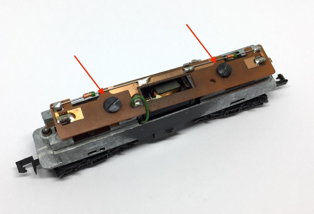
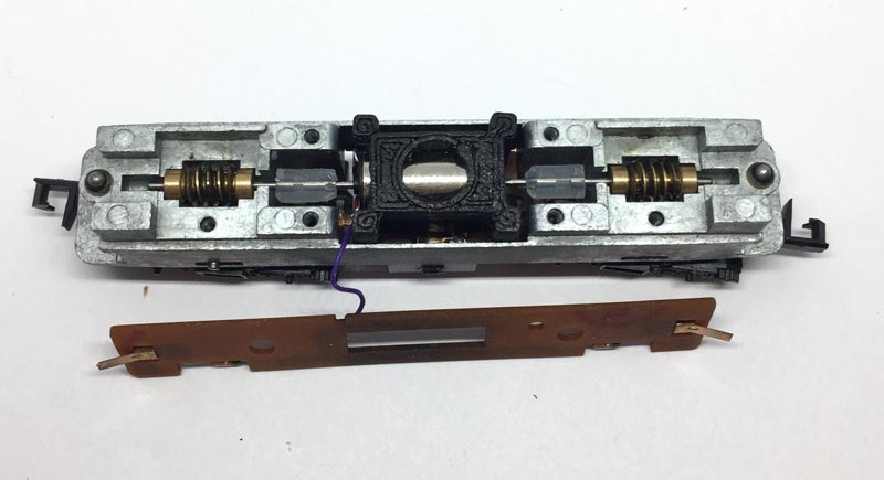
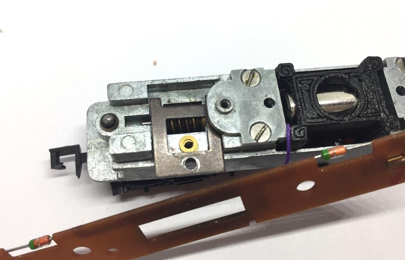
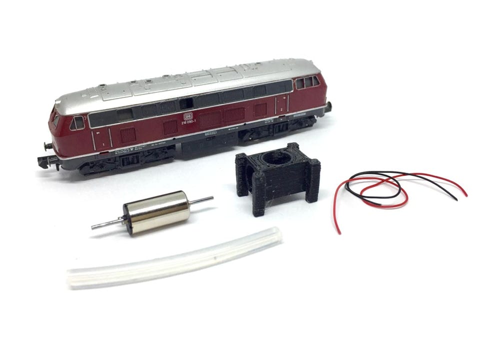
Conversion Minitrix BR216 V160

to 12V coreless motor

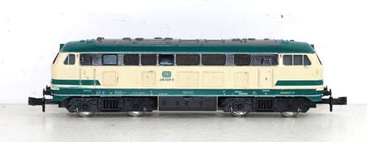
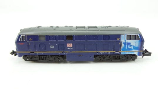
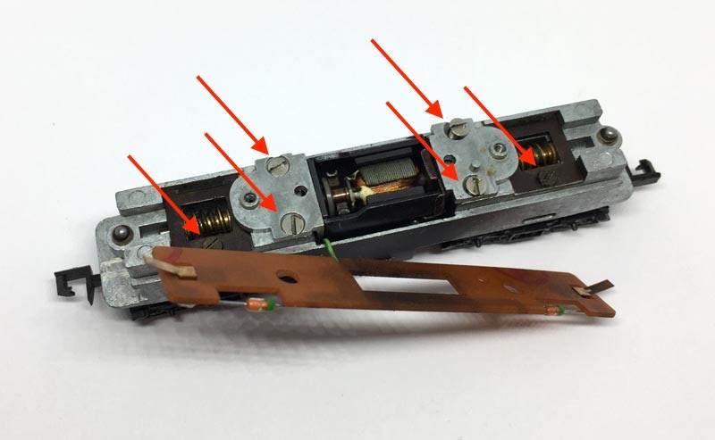
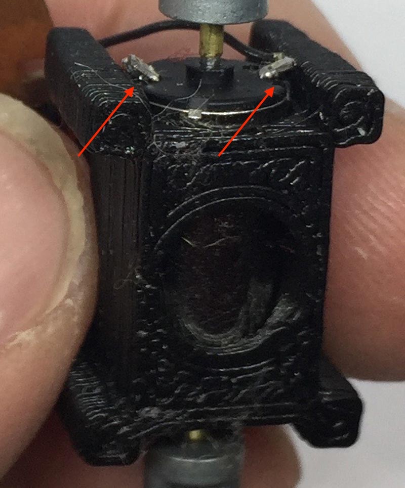
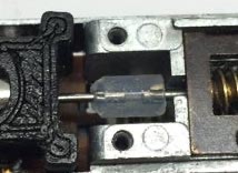
Fits all Minitrix art. 2959, 12873, 12952, 12953, 12501 (Years 1986-2002). Will even be suitable to similar designed Minitrix locomotives (compare inside of your model with the pictures).

What you need for conversion set

- The model and upgrade kit

- Small flat screwdriver

- Soldering iron 15W/25W

-Sharp pair of scissors or knife


Good to have:

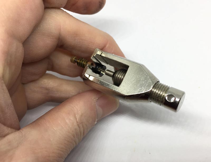
- Gear puller (get a brilliant one here)

(though plastic worms pull off quite easily by hand)


Installation time: Around 1 hour
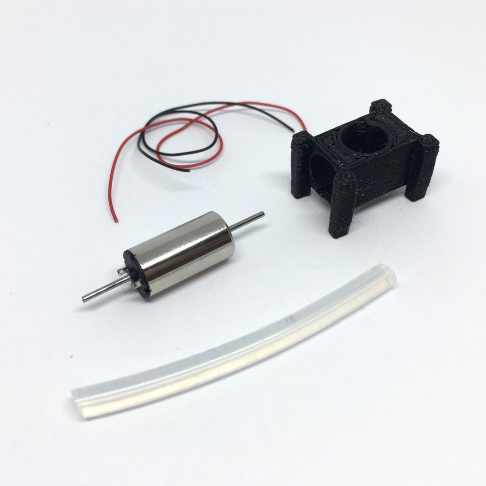
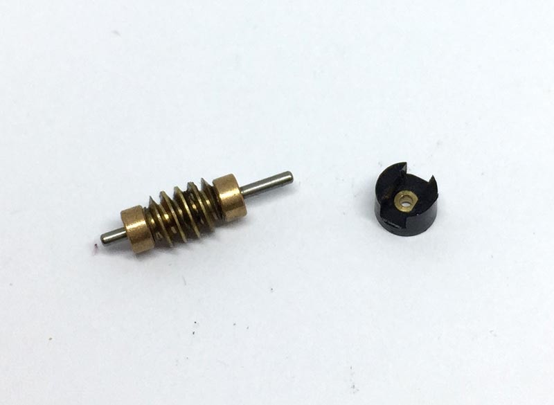
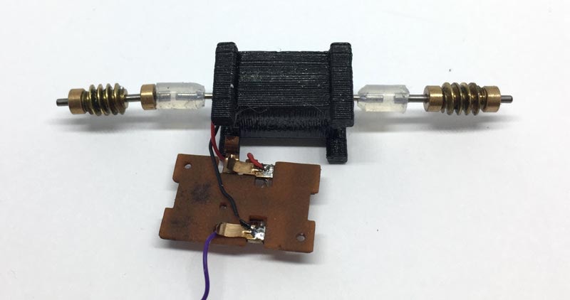
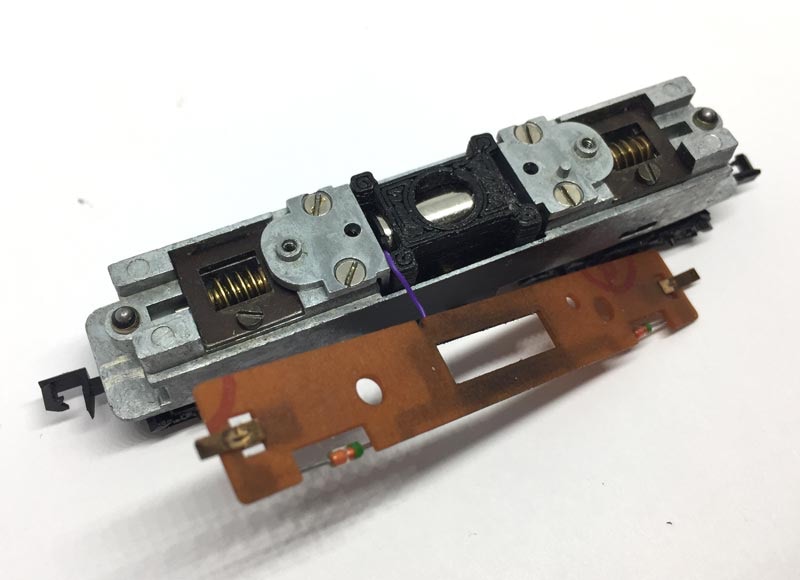
Contents of the kit

KASTENLOK INDEX

Question? Just reach out!

Take apart

1

Open model by pulling on the sides, as with most N gauge models.

2

Remove electronics board

Remove two large screws. Take PCB board off.  Careful with the washers under the screws. One of mine broke, off old age. Mind the two lamps on the fronts, put them aside. 


You can de-solder the green wire, to be able to put the PCB board aside, while you are working on the model.

3

Remove screws

Remove the screws and take out the 4 panes (including the motor) that the screws have been holding in place.

4

Remove screws from motor

After removing the motor,  you can put it aside. You don’t need it anymore for this train.

5

Take drive shaft connector off

This part has been pressed on by Minitrix, not glued. If you pull it off by hand, the black part will come off the brass insert.  You’ll need pliers to pull that off, as it is a very tight fit. 


The easy way is to use the Tramfabriek Gear Puller (pictured right), available here. This will also keep the item in tact (but for our upgrade project, you don’t need this anymore).

We only need the part at the left.

6

Widen the gap in metal bracket

As the silicone tube we are going to use has the same diameter as the hole it will go through, use a round file to widen the gap. This is optional, as you can also cut the edges of the silicone tube, so it is smaller at this spot (see step 9 in these instructions).

7

8

Protect motor from short circuit

The contacts of the motor will likely touch this metal plate. Tape the sides next to the hole, so a short circuit will avoided. Note that the two metal plates are different! One has an extra pin on top, that fits in the large PCB board. The other one is the one that goes on the motor contacts side and needs to be protected.

Solder wires and bend contacts

Push the contacts to the side with a flat screw driver. Next to one of the contacts, there is a small +. Connect the red wire to this contact. Solder the black wire to the other side.

9

10

Cut silicone tube to size

Cut two (close to exact) 7 mm long pieces of the silicone tube. Use a very sharp pair of scissors or very sharp knife. On the picture below you can see that I’ve cut the edges a bit round, so it won’t touch the metal bracket. Make sure that the other side is as straight as possible. Alternatively, you can also cut the edge round.

Assemble motor + worms

Put the whole thing together as on the picture. Solder the motor wires to the board. Connect the red wire to the contact where the copper strip is standing upwards, the one that is connecting the mass of the body to the right wheels.


Don’t get confused: I’ve replaced the green cable with a more flexible purple Ultra Thin wire. This, of course, is optional.

11

Place motor assembly in model

When putting the assembly back, be aware of the following:

- Placement of the silicone tubes: not rubbing the metal, between the tube and the worm.

- Routing of the green cable (here purple) to the light board. This will go along the front side of the motor.

- Placement of the PCB board in the bottom. Make sure it is placed in the middle, so everything fits well. The bottom of the two metal brackets keep it centred, so the brackets can be helpful to centre it.

12

Screw all the cover plates in place. Note the routing of the purple cable.


As you can see, I’ve added two washers (which create a 0.4 mm height) under the plate that hold the brass worm in place. This is not essential, but if the plates are screwed in place without, the train will not run, as there is not enough play for the worm. You can also use a piece of 0.4 or 0.5 mm styrene or card board to create the height or nothing at all and just loosen the screws a bit until the model runs.

Make sure bottom PCB board is centred and flat!

I had an issue of short circuit, which kept me busy for two hours, because I couldn’t find it. The tabs of one of the metal brackets (indicated by arrow) was touching the contact to the power pickup. If you experience a short when screwing one of the metal brackets in place, it helped to file a bit of the bottom of the metal tab.

13

Finished! Optional: a decoder

Test the model before closing and you have a very much improved model, which runs like you expect from a new model today.


If you want to install a decoder, there are now three places around the motor where this can be installed. Even on the bottom there is enough space for a Train-O-Matic Lokommander II Micro decoder (pictured), but also other small decoders can be fitted here (for example ESU Lokpilot 5 Micro, Kuhn N045). Though these can also be fitted on the side of the motor.