UK based

Prices for UK customers are shown inc 20% VAT

Other countries, inc EU, prices shown are ex VAT. 

upgrade to 12V coreless motor
Question? Just reach out!

This upgrade kit is for Graham Farish models in production 1981-2000: Art 8014, 8015, 8035, 8036, 8037, 8038, 803D, 803E and other compatible models.

Kit comes now with faster motor @ 17,800 RPM

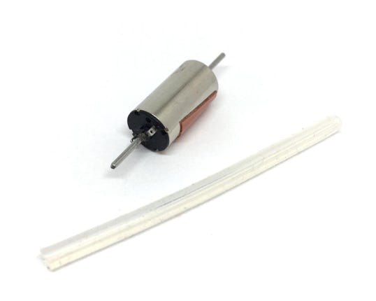
Contents of the kit

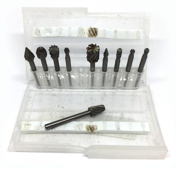
You’ll need to get a round milling bit like this, from for example eBay >>>

1

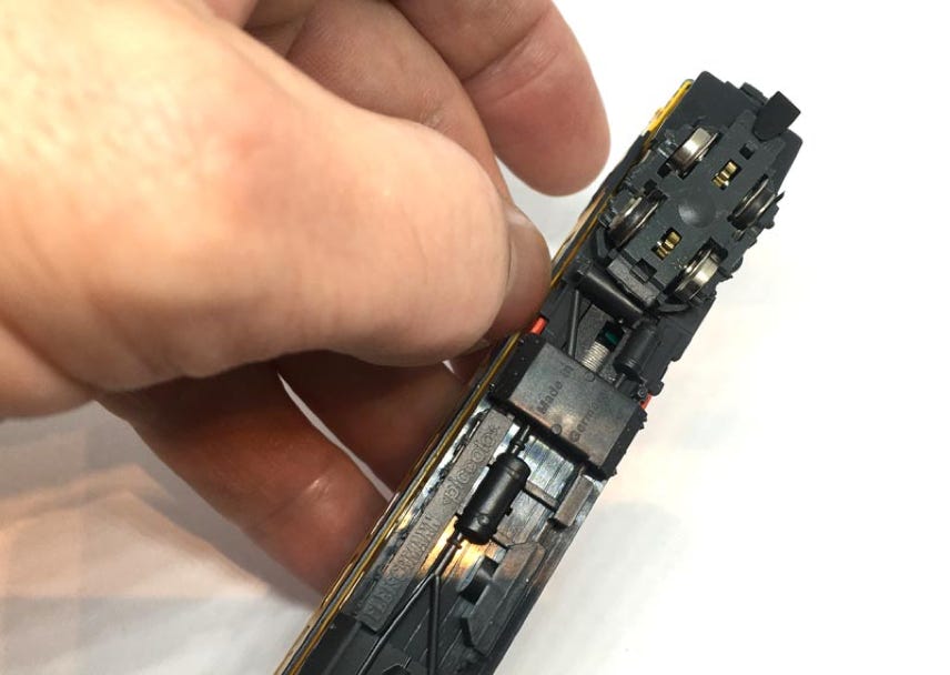
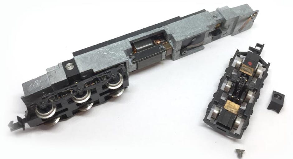
To open the model. Easiest is to use cocktail sticks on the four locations indicated. Then you can easily pull the chassis out (other model shown as example).

2

4

3

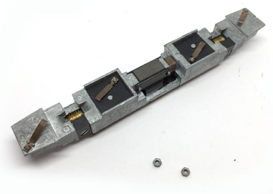
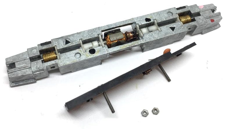
Remove the two screws and take the electronics board off. Two bolts will come off when you release the screws. Those are also holding the power contacts in place, so be careful not to loose those.

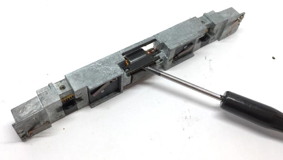
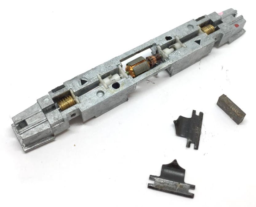
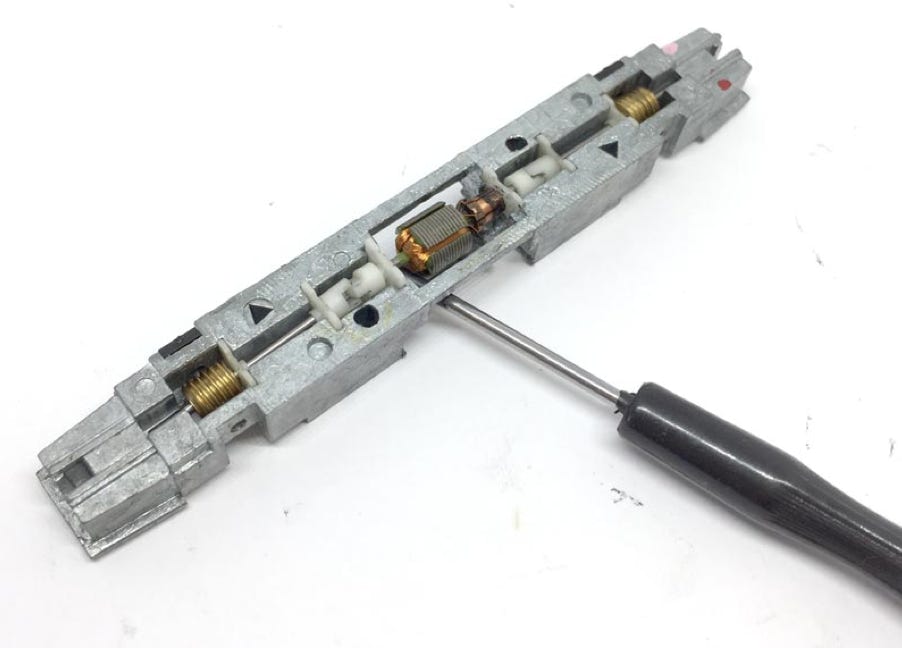
Remove the motor shield with a flat screw driver. All the parts that come off, including the motor brushes and springs, are not needed anymore.

What you need for conversion set

- The model and upgrade kit

- Small flat screwdriver

- Soldering iron 15W/25W

- Milling bit with round head


Installation time: Around 40 minutes

Difficulty: Pretty easy to do. Don’t let the milling scare you off. With the right milling bit, it’s easily done.

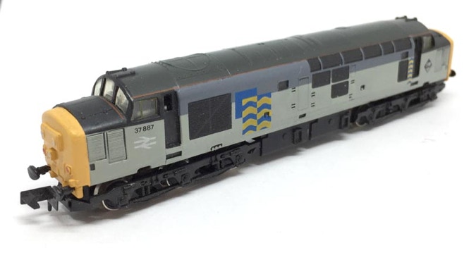
Graham Farish Class 37

KASTENLOK INDEX

IMPORTANT INFORMATION: SPLIT GEARS

Check the gears on the wheelaxles. On my model, 5 out of the 6 gears where split. You need to replace any split gear in order to have a well running model. These 16 teeth gears (Bachmann art GF2504) come in packs of 6 and are not expensive. They can be bought from 'farishnspares' in the UK, who ship world wide. With a Tramfabriek Gear Puller one wheel can be taken off and after replacing the gear with your fingers, you can press the wheel back on with a vice. It really is not a difficult job. Be aware of the spring of the coupling that might jump out, when you remove the bottom of the bogie. 

Remove both of the bogies (US: trucks) by taking out one screw above the bogie.
5

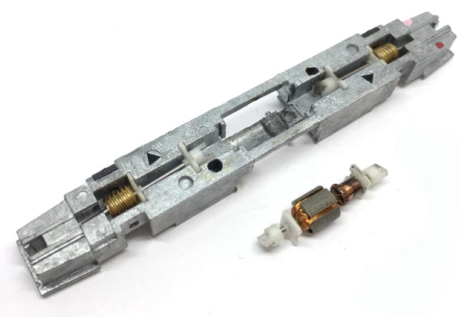
Remove the motor by lifting the two white plastic pieces on each side of the motor straight up.

6

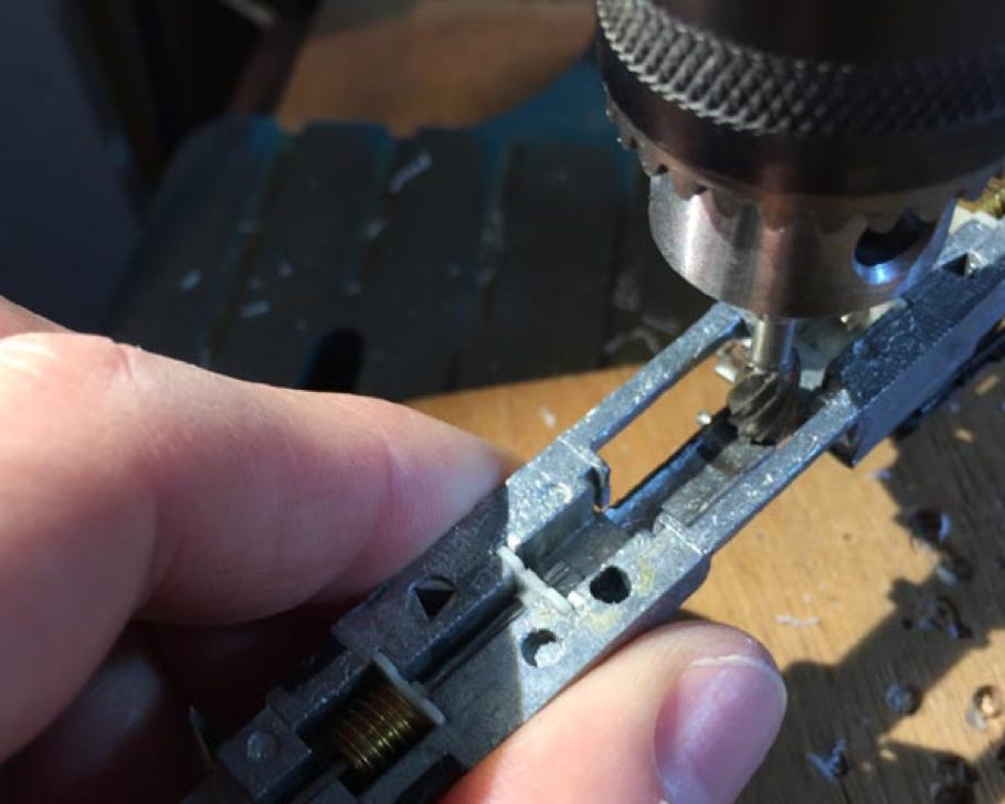
Milling example

7

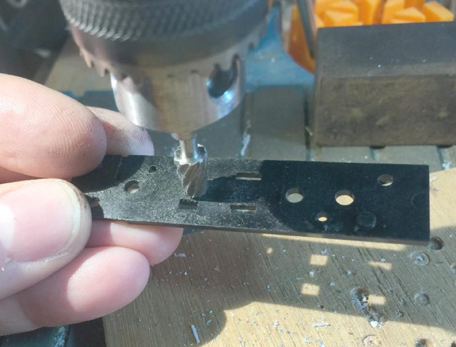
While you are milling, also make more space for the motor on the bottom side of the plastic chassis cover plate, using the same mill bit. Only a tiny bit needs to be removed, around the hole that previously was holding the motor brush.

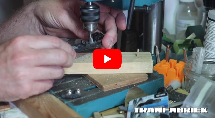
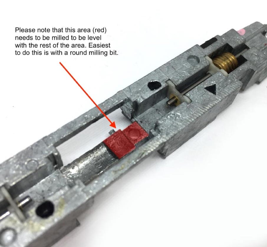
The Tramfabriek upgrade kit is designed so that there is a minimale need for milling. Only the red indicated part needs to be levelled with the part you see on the left of it, so the motor fits flat. Watch the video to see how to mill in an easy way, if you don’t have any or little experience. It really isn’t difficult. Don’t forget to put (safety) glasses on, to protect your eyes from small metal pieces. But it’s more messy than dangerous.

8

A few steps have to be taken here:

A) Cut two pieces of the silicone tube, each about 9 mm in length.

B) Solder wires to the motor. The orange wire is soldered to the motor contact that has a plus (+) next to it.  Leave the end bare, as the wires will have to make contact with the chassis (analogue only!). When the electronics board is fitted, the cover plate will press the wire against the metal chassis.

C) When pressing the motor in place, easiest is to have the silicone already fitted on the motor. Then take the tape protection from the motor, then press is in the chassis. Align the motor side without the contacts to the metal, so the contacts on the other side do not touch the metal. Bend the contacts a bit inwards for extra safety.

9

After screwing the chassis cover plate back in place. Check if it fits well on motor. You can see from the side if the motor is straight. If the motor is slightly angled, it means the cover plate is pressing it down on one side. Then you have mill a bit more.  The orange (+ from the motor) should now be pressed between the chassis and cover plate and transfers power from the wheels to the chassis to the motor.

Route the grey cable through one of the holes and solder it anywhere on the brass strip (not shown).

10

Test the model and compare it to the running direction of another model. If it runs in the opposite direction, you have to swap the wires to the motor.

Digital conversion

This motor upgrade kit can very well be converted to DCC. For great decoders, check here. Check the digital setting page, for many decoders, to get the best driving experience.

And one more model has been brought back to the future!