

UK based
Prices for UK customers are shown inc 20% VAT
Other countries, inc EU, prices shown are ex VAT.

KASTENLOK INDEX


UK based
Prices for UK customers are shown inc 20% VAT
Other countries, inc EU, prices shown are ex VAT.

KASTENLOK INDEX
Fits on many, many other Graham Farish models with a similar motor design. If you are going to try this on your own, not listed model, be aware that there is one alternative upgrade. The only difference between the kits is the size of the worm. If you are in doubt, get the kit from this page and purchase the Tramfabriek part TFWOR3 (larger worm) with it, so you have both worms.
Please note: if you hear and see a bump, every wheel rotation, it is likely that the gear is split. You can order a replacement 25 teeth gear from BR Lines.
Instructions
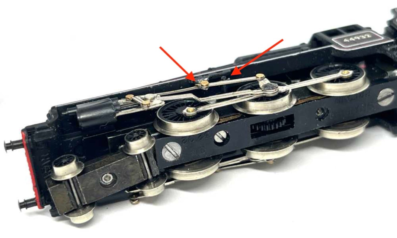
Test the workings of the drive and fit the housing. Hook the back of the chassis inside the cab end and then close the front. Be careful to make sure the valve gear slides behind the raised parts in the housing (see red arrows). Don’t forget to place the front bogie and close the model by fitting the screw.
That’s it, another vintage model has been given a new lease of life.
Please note: if you hear and see a bump, every wheel rotation, it is likely that the gear is split. You can order a replacement 25 teeth gear from BR Lines.
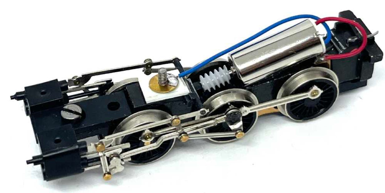
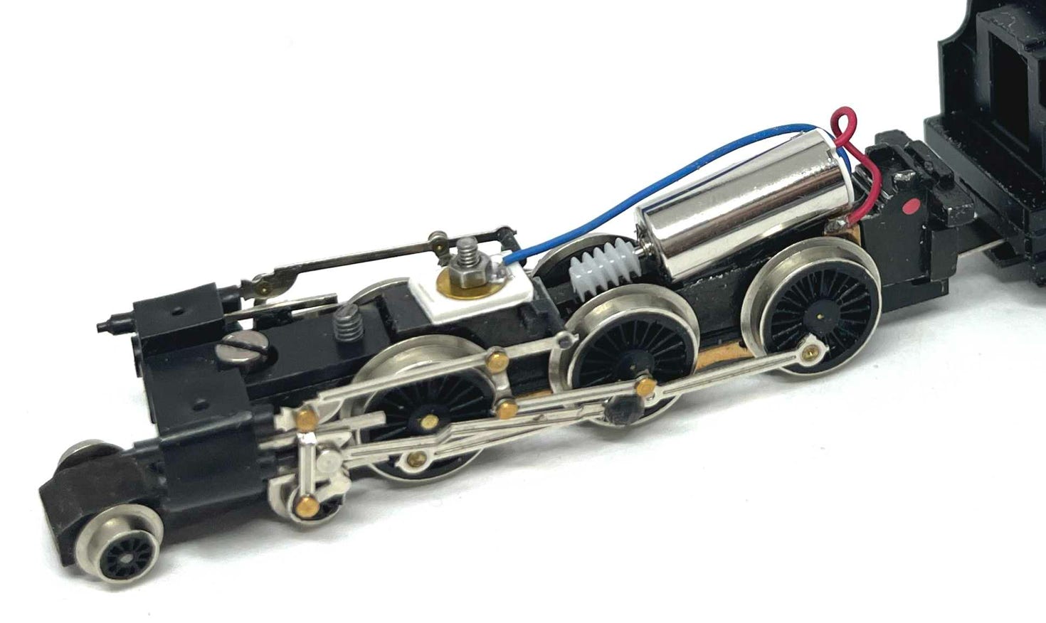
Follow the Class 08 (Poole) instructions how to take the model apart, by clicking here: INSTRUCTIONS. What will be different is the fitting of the screw, that is leading the power from the one side of the pickups to one contact of the motor (blue wire). There is a bar that also holds the gearing in place and this needs to be held down. The two top rods on each side are connected to it.
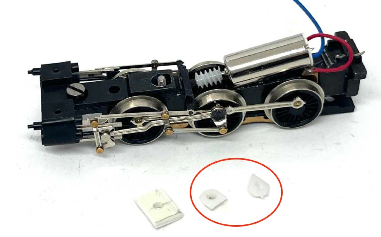
You need one of the two white plastic parts that are left over from the motor assembly.
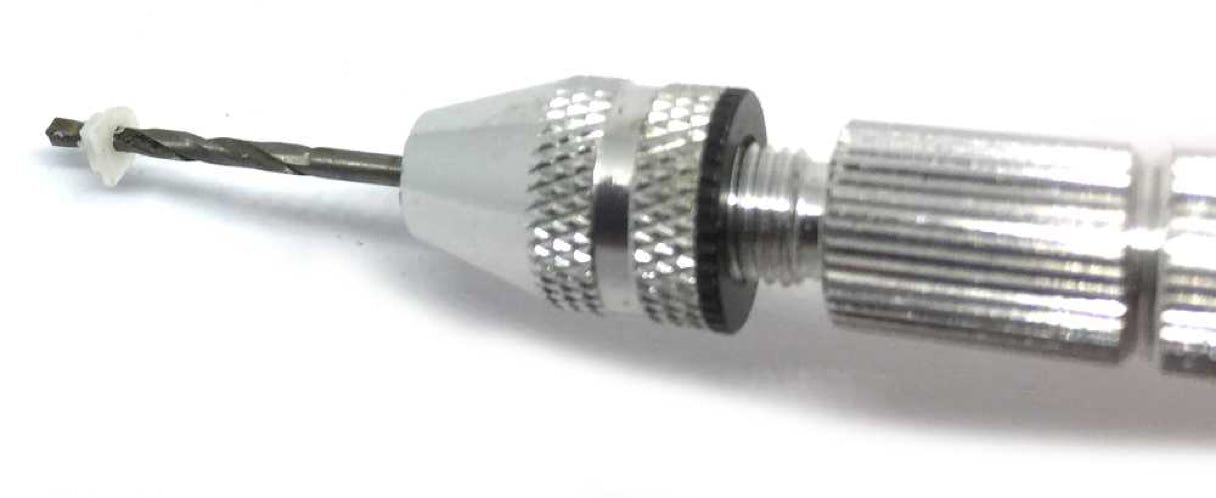
With an 1.7 mm drill bit and a hand vice, drill a hole through the plastic.
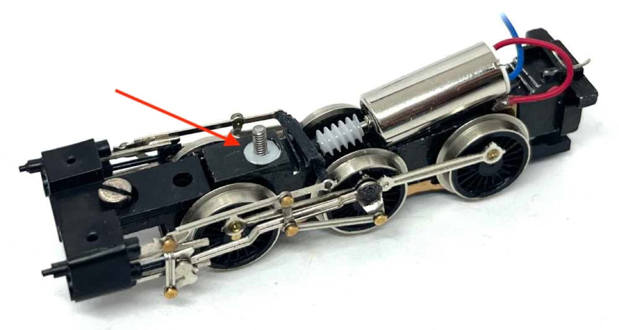
Cut the two square corners of the plastic thingy, so it’s more round and press it in the hole indicated. The M1.6 screw can now be pressed through it. This plastic piece assures that the screw stays centred and is not touching the frame, to avoid an electronic short.
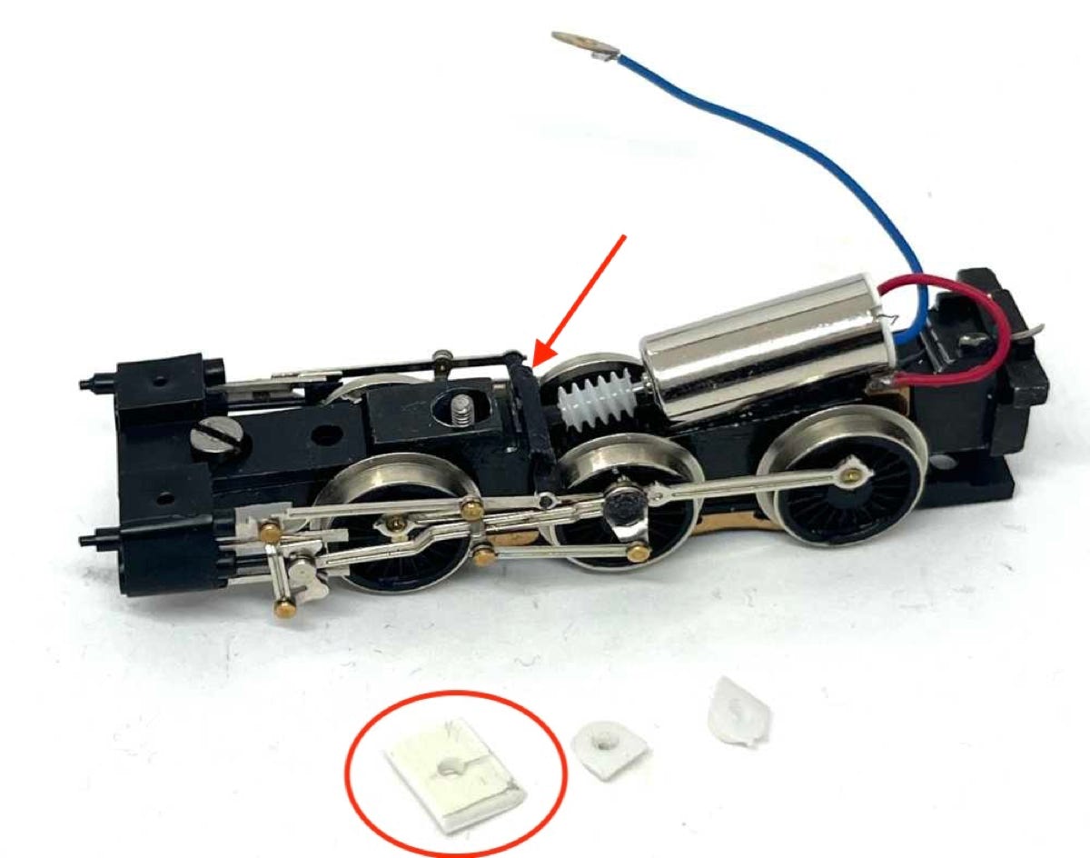
Now you need a piece of styreen. I used 1mm thick styrene. It needs to be the width of the part it will be placed on, so about 6mm. The length of this piece should be that it presses on the bar (see red arrow) that holds the gearing in place. The length of the other end shouldn’t be too long, as the housing will fall on the front part of that area of the chassis.
With the hand vice, use the same 1.7 mm drill as before and drill a hole. Use a centre punch to make the starting point.
Slide the styrene piece over the screw.
Solder the wire to the brass ring supplied and fit this on the screw.
Finally, fit the bold.
•