UK based
Prices for UK customers are shown inc 20% VAT
Other countries, inc EU, prices shown are ex VAT.
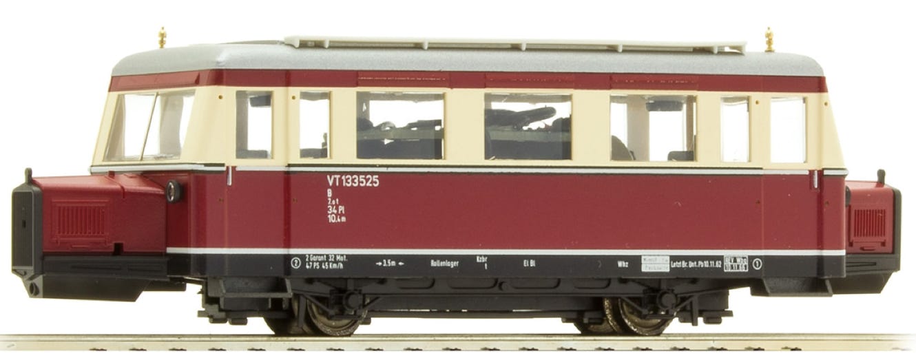
Fits Bemo without flywheel with wheelbase 46.2 mm, Art 1609 906 H0e/H0m and HO.
Conversion Bemo Wismar Railbus (older version)
to 12V coreless motor
What you need for conversion set
- The model and upgrade kit
- Small flat screwdriver
- Soldering iron 15W/25W
- Thin wire (get the thinnest wire here)
Good to have:
- General modelling tools
Installation time: Around 45 minutes
Art. BE1006-1
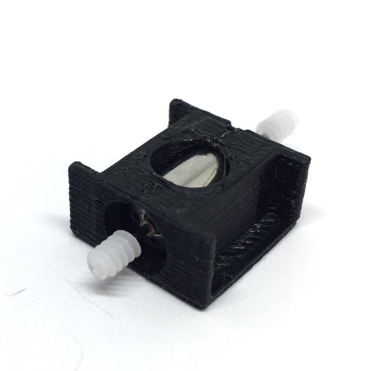
Contents of the kit
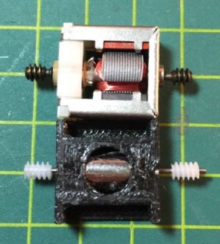
1x 8x16 mm motor
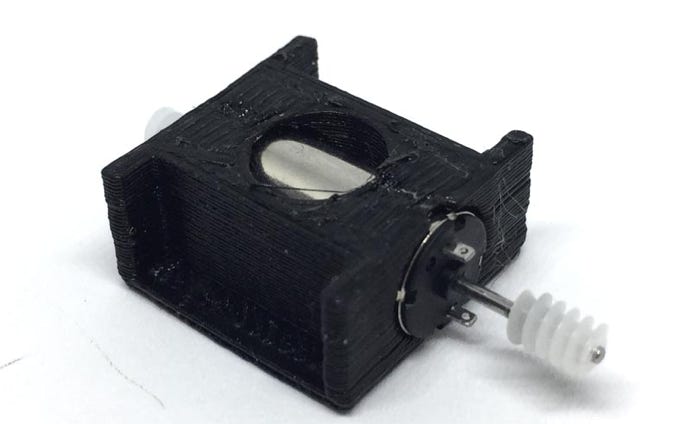
1x motor casing
2x M0.3 worm
1
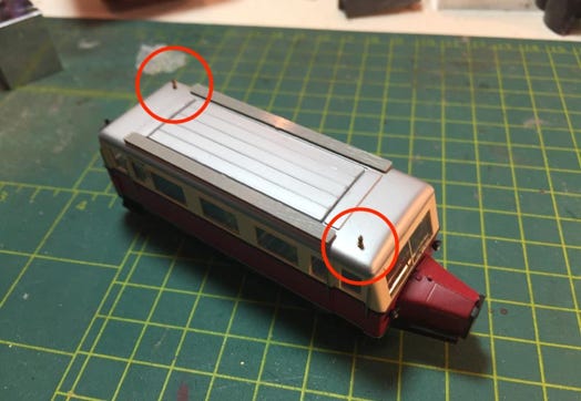
Take note of the fragile parts
2
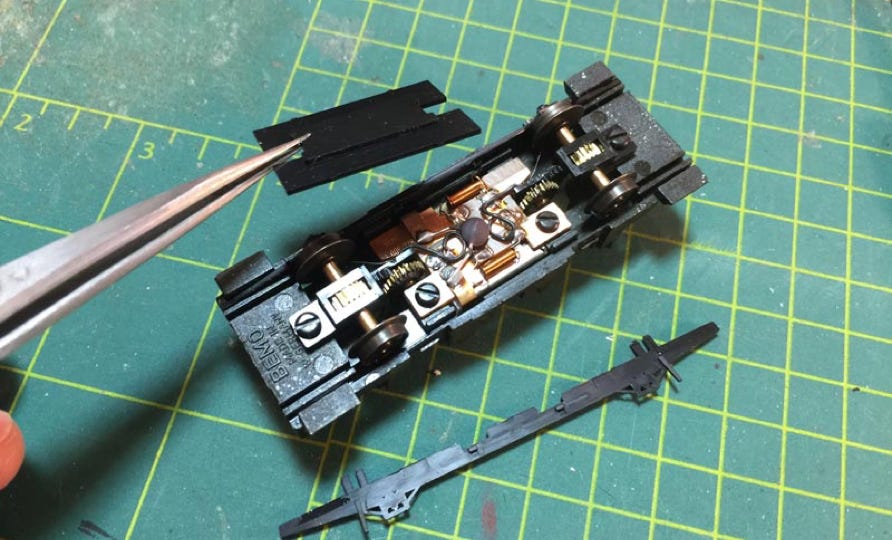
Take the housing off
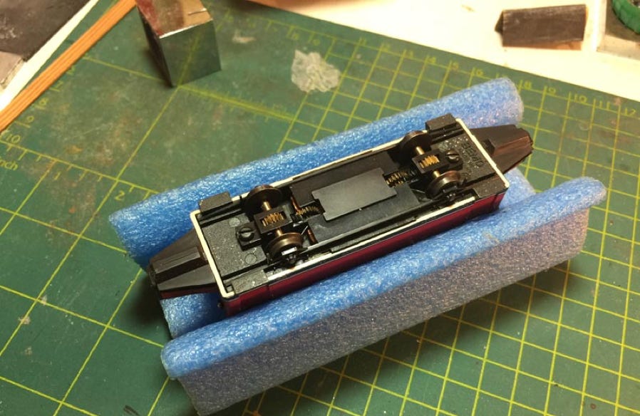
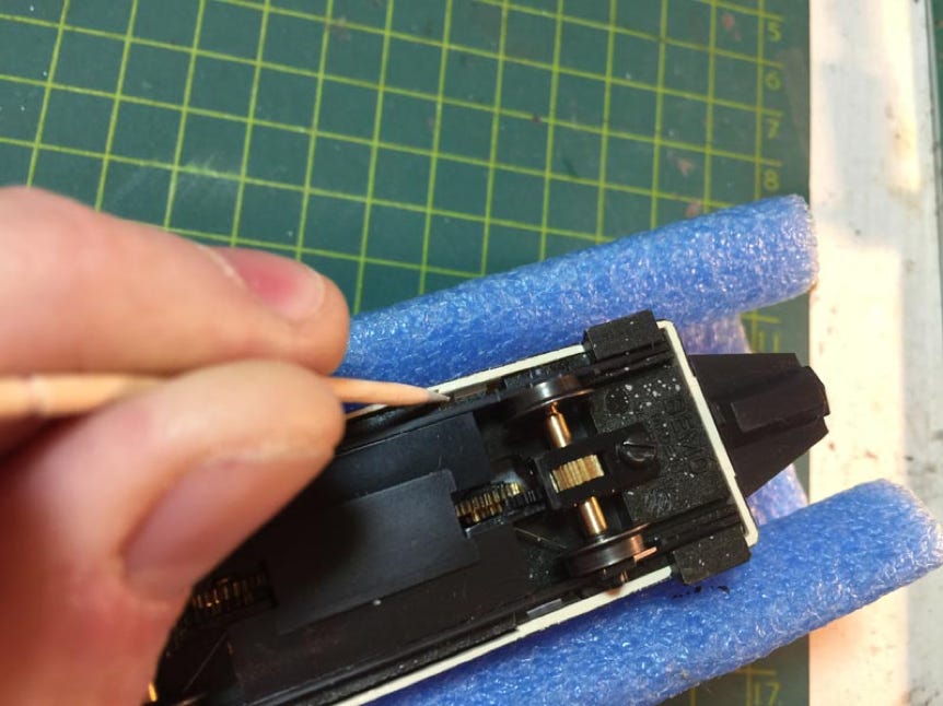
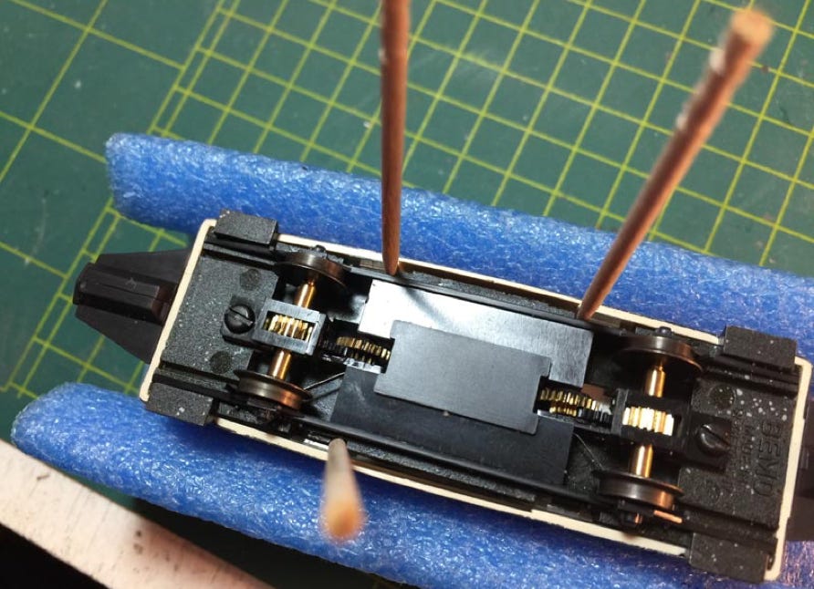
The bottom part has 4 tabs that fit into holes in the window panels. The biggest mistake people make here, including me, is to put the cocktail stick between the outer body housing and the window, but it should be between the black bottom frame and the window. If you pull the body out with force, you would break the clips in the window panels. Put the body housing aside.
3
Remove on of the side skirts, by just pulling it upwards (towards you). This will also release the bottom panel, as it is the side skirts that hold this panel in place (important to know when re-assembling the model).
Taking apart the bottom frame
4
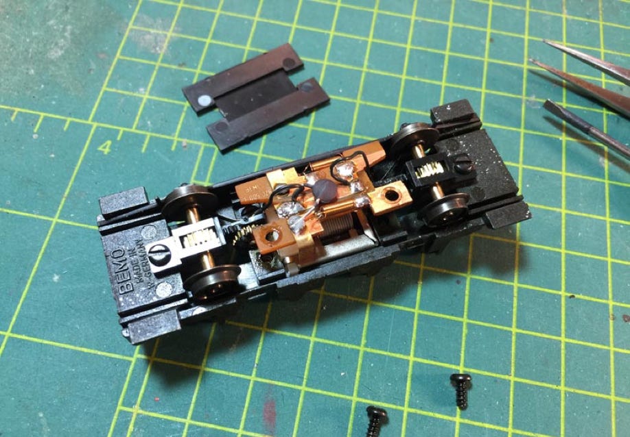
Remove the screws in the PCB board. Don’t loose them.
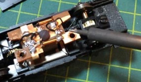
De-solder wires
The wires can actually stay connected to the model for later use, but I decided to replace these clumsy wires for Ultra thin wire.
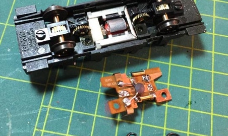
Take the PCB out, which will reveal the motor.
6
7
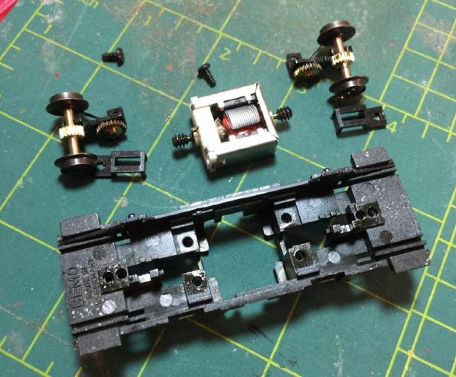
Remove all items
When you unscrew the two screws next to the axles, you can take the whole assembly out. Take good notice on how it all fits together and how the parts hold each other in place.
Solder wires
For your convenience, the motor has already been fitted in the casing by the Tramfabriek. Notice that the contacts should face upwards. Top will be + (see small sign next to contact). The motor is not been pushed in completely. After soldering the wires to the motor, push the motor completely in the casing until it can’t go further.
9
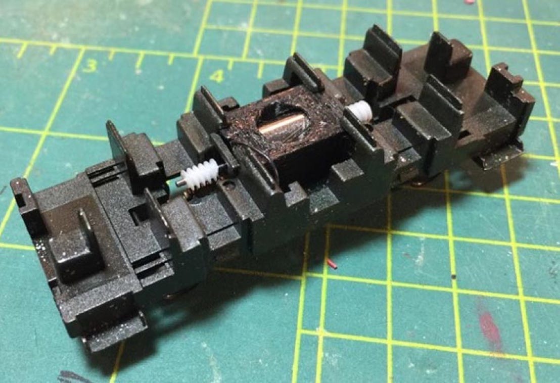
Fit motor
You should be able to push the motor assembly in place and by design it will stay in place by friction. If you want to be sure, you can add a bit of glue on it, but it hasn’t been necessary with my model.
Note that the + wire is black, instead of the traditional red. This way it is not obvious when looking inside the model. This wire goes out from the top, then goes down to the PCB through a gap on the side. The - wire goes directly to the bottom. This is why the contact pins are positioned vertically.
10
Reassemble model
Test if it runs well, then close the model.
Digital conversion
This motor upgrade kit can very well be converted to DCC. Check the digital setting page, for many decoders, to get the best driving experience.
•