UK based

Prices for UK customers are shown inc 20% VAT

Other countries, inc EU, prices shown are ex VAT. 

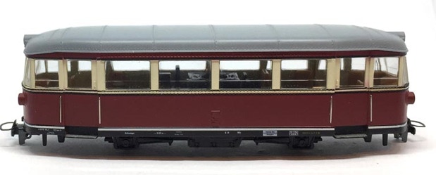
Conversion Bemo Fliegender Spreewalder

to 12V coreless motor

Fits Bemo Art 1233 833, 1233 813 H0e/H0m.

What you need for conversion set

- The model and upgrade kit

- Small flat screwdriver

- Soldering iron 15W/25W

- Thin wire (get the thinnest wire here)


Good to have:

- General modelling tools


Installation time: Around 45 minutes

Art. code: BESPREE


Contents of the kit

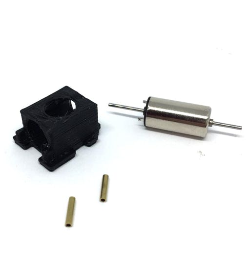
1x 8x16 mm motor double shaft

1x motor casing

2x brass adapters
KASTENLOK INDEX

Question? Just reach out!

1

Remove housing

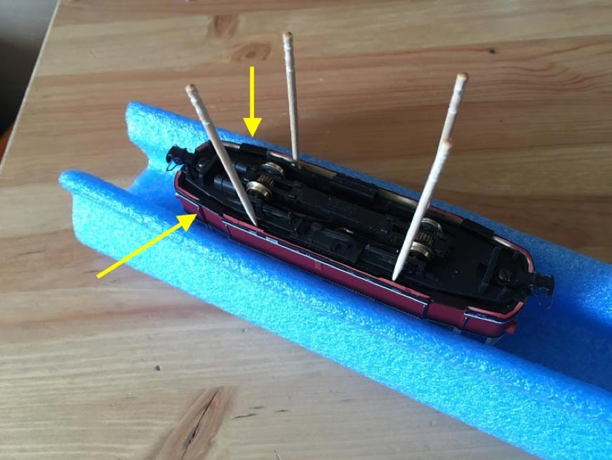
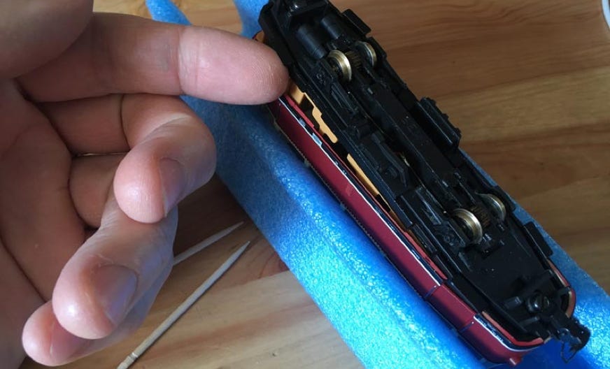
The bottom part has 4 tabs that fit into holes in the window panels. The biggest mistake people make doing this for the first time, including me, is to put the cocktail stick between the outer body housing and the window, but it should be between the black bottom frame and the window. If you pull the body out with force, you would break the clips in the window panels. Put the body housing aside. On the image I’ve used four cocktail sticks, but two on one side are actually enough, then lift it from the doorsteps (yellow arrows).

6

7

4

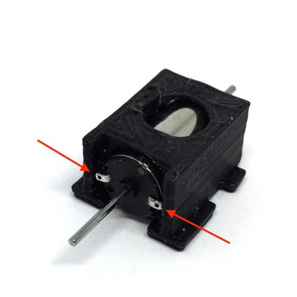
Check if the contacts are bent outwards. If not, do this by rolling the shaft of a small screw driver over it.

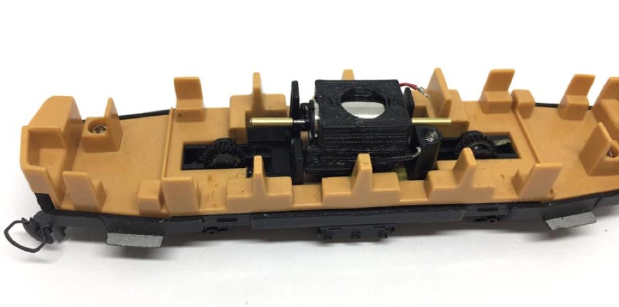
Glue the brass adapters as pictured. Loctite or Superglue can be used.  Then place the motor in the model, not pushing it down to the end, but just loose in the model.

2

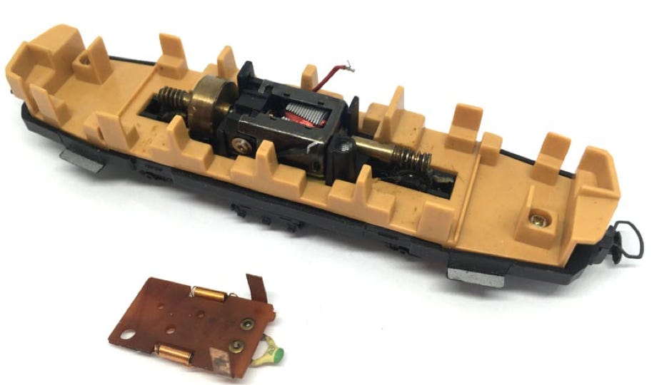
You can now remove the motor, it just lifts straight out.

5

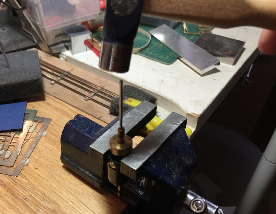
Take the brass worm/flywheel off the axles. You can get more tips on how to this here.

8

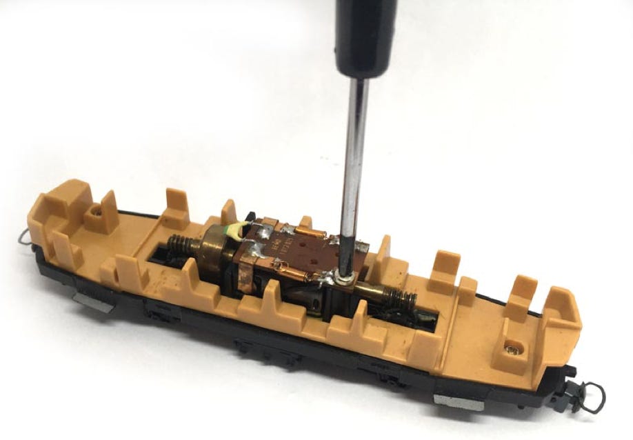
Remove screw and take the electronics board off. The two driver’s cabine wall pieces have been taken off as well.

3

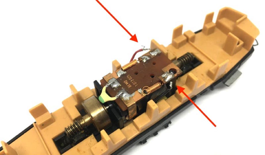
De-solder the two wires.

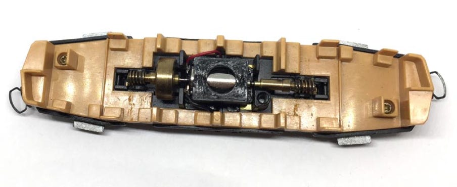
Before you start fitting the worms, check if the motor is completely pushed in the black motor casing. 


First, check the location of the left worm with flywheel and glue it at the correct position. The worm should be vertically centred with the gear under it. Then test fit the right worm, making sure you don’t push the motor out of its position in the casing. Then when you know where it has to go, glue the worm on the motor shaft. Press the motor assembly now down in place. It should stay in place by friction. If you want to be sure, use a little glue to keep it in place. Or fit the electronics board back on. But then you’ll see this through the windows.

9

You’re done! Test the model before putting the housing back on. If everything works well, press housing and chassis together. Or fit DCC, sound and/or a Powerpack (see below)

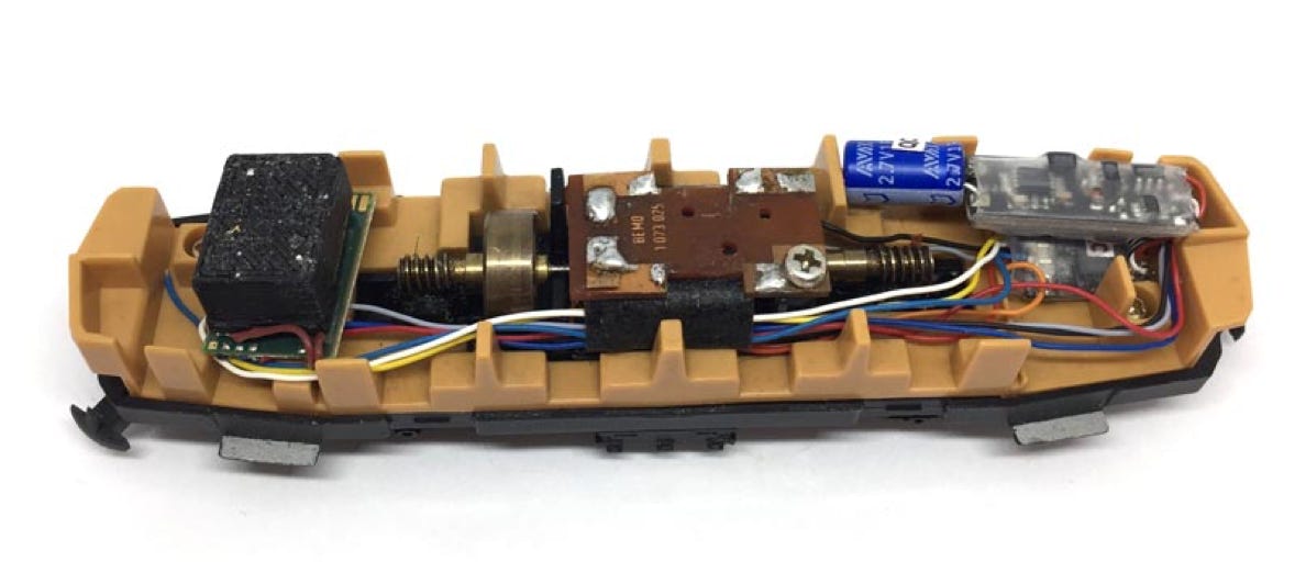
This motor upgrade kit can very well be converted to DCC. Check the digital setting page, for many decoders, to get the best driving experience.


For the conversion at the right, I’ve used the Train-O-Matic Micro decoder with wires (art. 02010223), the SPP-N Powerpack from the same brand and a SUSI sound decoder from Doehler & Haass.

Digital conversion