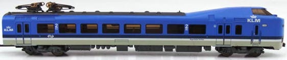
Minitrix Koploper Upgrade

to 12V coreless motor

KASTENLOK INDEX

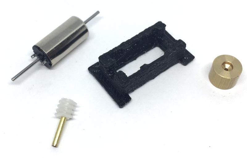
What you need for conversion set

- The model and upgrade kit

- Small flat screwdriver

- Soldering iron 15W/25W

- Something to cut


Installation time: Around 40 minutes

Difficulty: Pretty easy to do. Just make sure to keep an eye on the small parts of the model itself when opening the model.

1

3

Fits Minitrix art. 12184, 12500, 12749, 12829, 12865
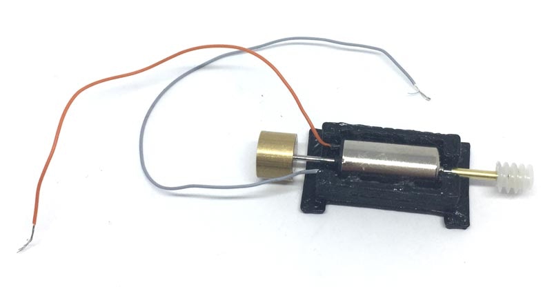
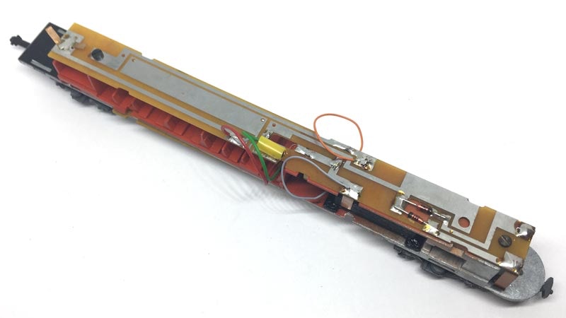
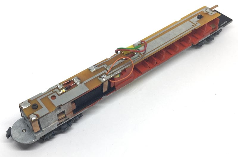
Contents of the kit

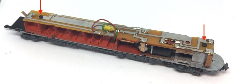
To open the model, easiest is to use cocktail sticks on the four locations indicated. Then you can easily pull the chassis out.

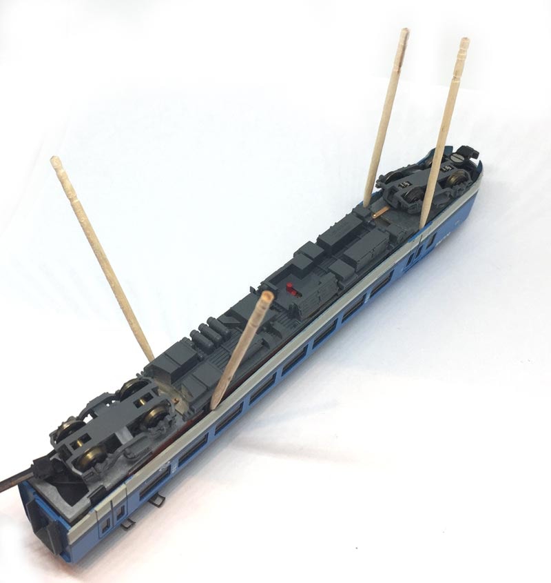
Om het model open te maken is het het makkelijkst om vier cocktail prikkers op de aangegeven plekken te plaatsen. Je kunt het onderstel dan makkelijk uitnemen.

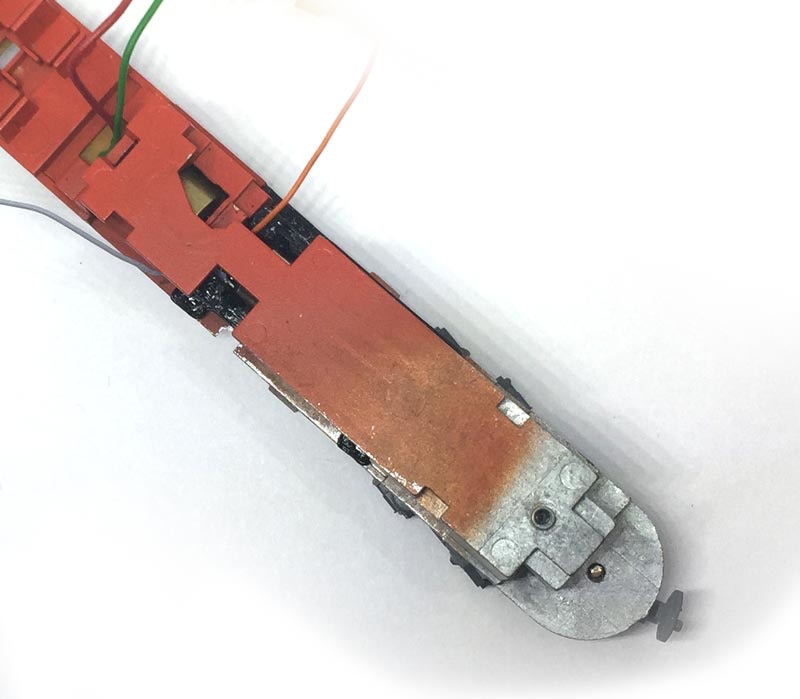
Remove the bottom by un-clipping the four hooks.  Two on the side pictured below, two on the other side. If you fail to take this off, you will damage one clip when you slide the new motor in. 

2

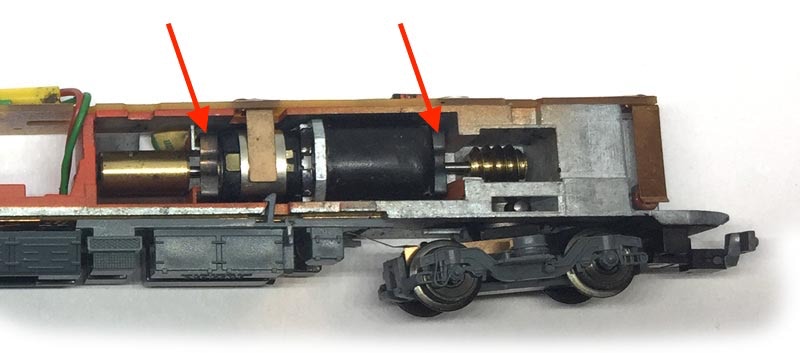
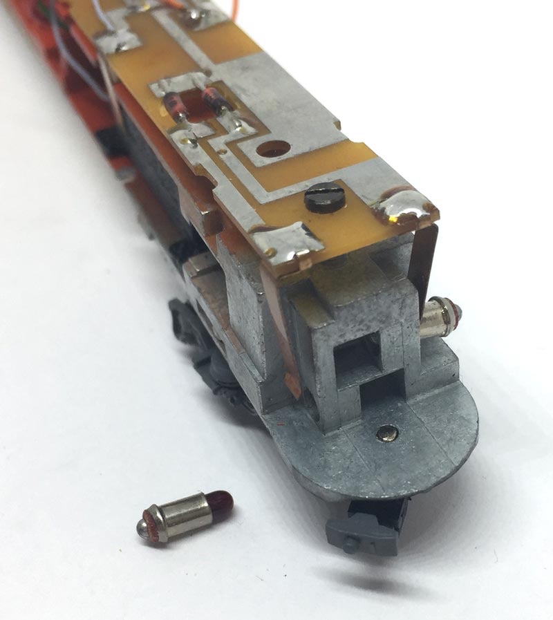
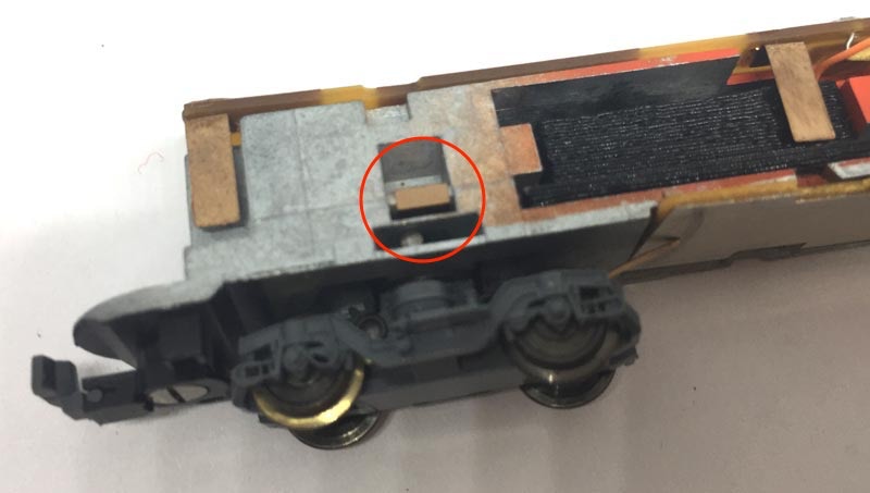
Take note of this very small phosphor bronze item (“kontaktfeder” Minitrix art 13 2956 15). Take it out before you loose it. It will fall out and disappear during the re-motoring, if you don’t remove it.

Let op het hele kleine fosforbronzen onderdeel (“kontaktfeder” Minitrix art 13 2956 15). Neem het eruit en bewaar het goed. Het verdwijnt tijdens de verbouwing als je dit laat zitten.

Question? Just reach out!

5

The original motor is held in place with two clips. You can remove these clips from the other side as pictured. You push the feet of the clips with a flat screw driver, and the clips and motor will slide out.

Om de onderzijde eruit te nemen, maak je de vier clipjes los. Twee aan deze zijde, twee aan de andere zijde. Als je de onderzijde laat zitten, breek een clipje af als je de nieuwe motor er in schuift.

4

Remove the two screws and take the electronics board off. Put the two light bulbs aside.

Verwijder de twee schroeven om het printplaatje los te halen. Leg de twee lampjes apart.

De originele motor wordt eruit gehaald door de twee clips los te maken die de motor op z’n plek houden. Je doet dit door aan de andere zijde dan afgebeeld de voetjes van die clips los te duwen met een smalle, platte schroevendraaier en het hele boeltje schuift er zo uit.

6

Assemble the motor like on the picture. The motor has a small plus (+) next to one of the connectors. That is the orange wire on the picture. To assure your model drives in the same direction as your other trains, make sure the plus will be on the left side (seen in forward direction of the train). You probably don’t have to glue the adapter with the gear, nor the flywheel and they’ll fit with a push fit. If you need glue because one of the items moves easily, use Loctite or superglue. Careful not to spill in in the motor.

Stel de motor samen zoals op het plaatje. De motor heeft een kleine plus (+) naast een van de connectors. Dat is het oranje draadje op het plaatje. Om er zeker van te zijn dat je model in dezelfde richting rijdt als je andere treinen, zorg ervoor dat de plus aan de linkerkant zit (gezien in de richting van de voorkant van de trein). Waarschijnlijk heb je geen lijm nodig om het vliegwiel en de wormadapter vast te zetten en zit het al met frictie vast. Maar zit het toch te los, een beetje Loctite of superlijm gebruiken. Oppassen dat het niet in de motor komt.

7

Slide the motor assembly inside the model. It will be obvious that you have to align the edges of the motor casing to the chassis. Position the flywheel that is doesn’t touch the chassis metal and wormadapter so that the worm is centred above the gear. Arrow: The Plus cable has be guided via the top of the motor, otherwise the motor casing doesn’t slide in.

8

When fitting the electronics board, here’s a reminder where the white and red light bulbs go.

Wanneer je de printplaat terugplaatst, hier is een geheugensteuntje waar het rode en witte lampje gaat.

9

Schuif het motorgeheel recht naar binnen, zodat de zijkanten van de motorbehuizing mooi aansluiten aan de zijkant van het metalen onderstel. Zorg dat het vliegwiel zo gepositioneerd is dat het het metaal van het chassis niet raak. Schuif de wormadapter zo dat de worm recht boven het tandrad van het draaistel staat.

When you have secured the electronics board with the two screws (M1.6, if you lost one), solder the wires on the board where the contacts for the previous motor are.

The motor can also be controlled with a digital decoder. The CV settings for several brands are listed here.

Als je de printplaat op zijn plaats hebt bevestigd met de twee schroefjes (M1.6, als je er eentje kwijt bent geraakt), soldeer dan de draadjes waar de contacten voor de oude motor zijn gesoldeerd. 

De motor kan uiteraard ook digitaal aangestuurd worden, de CV instellingen voor verschillende merken staan hier.

10

Niet vergeten om dat kleine, fosforbronzen dingetje weer te plaatsen. Test het model en als alles perfect rijdt, plaats de behuizing. Zorg dat de draden niet naar beneden hangen, anders zijn ze zichtbaar door de ramen. Mocht het model ratelen, dan moet u zeer waarschijnlijk de worm iets verschuiven.


CV instellingen voor digitale rijders staan hier.

Don’t forget to replace that small, phosphor bronze thingy! Test it and when it’s all running perfectly, place the housing again. If you hear a rattling sound, you most likely have to tune (=move) the worm a bit. Move the wires to the top or make them shorter than I have them on the picture, otherwise you’ll see it through the windows.


CV settings for digital use can be found here.

Digital conversion

This motor upgrade kit can very well be converted to DCC. Check the digital setting page, for many decoders, to get the best driving experience.

Deze motor upgrade kit kan ook aangestuurd worden door DCC. Kijk op de digitale instellingen pagina voor de CV instellingen voor de grote decodermerken, om de beste rijervaring te hebben.

And one more model has been brought back to the future!