

UK based
Prices for UK customers are shown inc 20% VAT
Other countries, inc EU, prices shown are ex VAT.


UK based
Prices for UK customers are shown inc 20% VAT
Other countries, inc EU, prices shown are ex VAT.
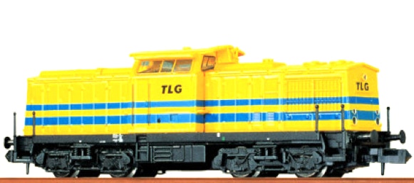
Conversion Brawa V100
to 12V coreless motor
Fits Brawa art 1415, 1416, 1422, 1425, 1427, 1428, 61100, 61101, 61102, 61103 61104, 61105, 61106, 61107, 61108, 61109
Question? Just reach out!
What you need for conversion set
- The model and upgrade kit
- Small Phillips screwdriver
- Soldering iron 15W/25W
- General model making tools
Installation time: Around 60 minutes
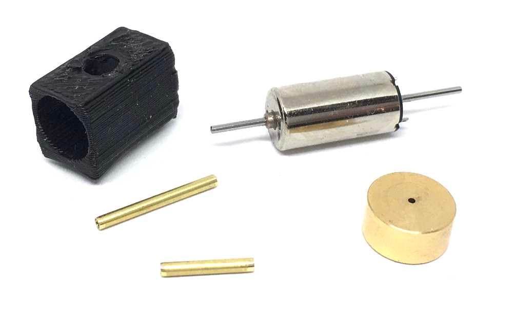
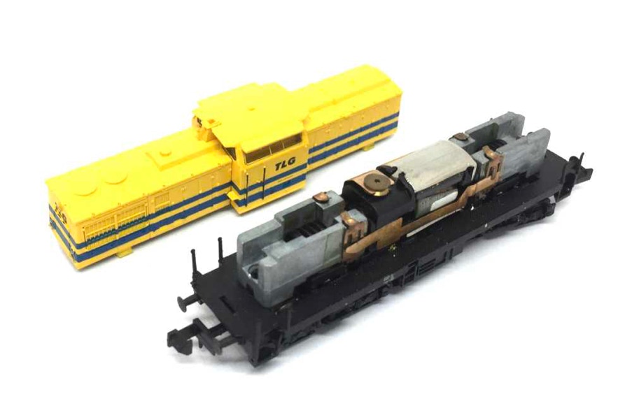
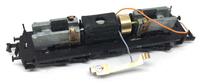
Contents of the kit.
This replacement might possibly fit in other Brawa N gauge models, so compare the measurements of your motor.
1
2
3
5
7
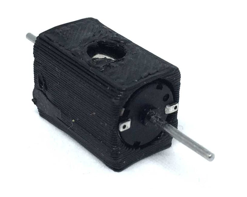
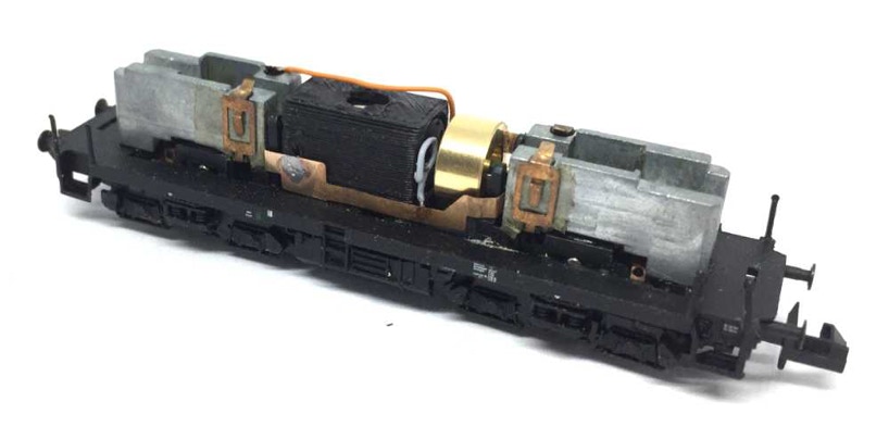
A small piece of 1 mm double side tape should have been fitted on the underside of the motor casing. But you can also use superglue to hold the motor in place, instead of the tape. It’s just an extra measurement. Even without it, this assembly doesn’t really move.
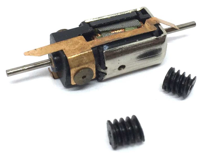
Take apart
Squeeze the front with your fingers, to release the tabs on the bottom of the housing from the metal frame. I find it actually easier to use a flat screw driver on the bottom of the metal frame and push the tabs inwards.
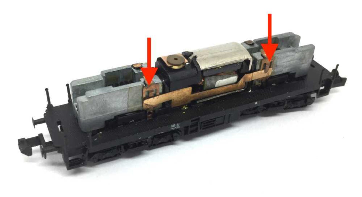
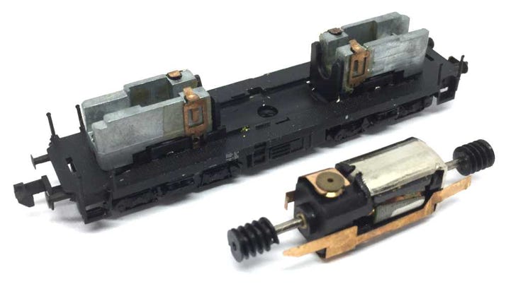
Release the copper strips from their clips and you can take the motor out.
The worms can be easily taken off by pulling with your fingers.
4
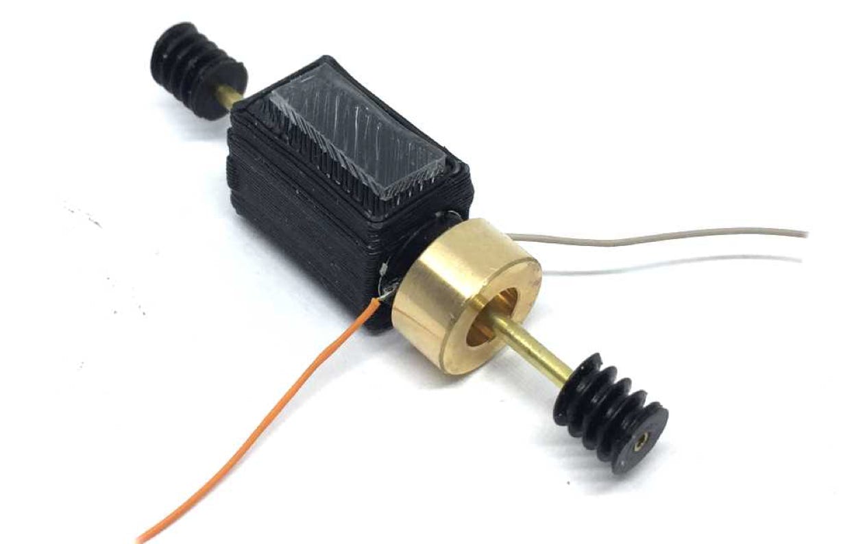
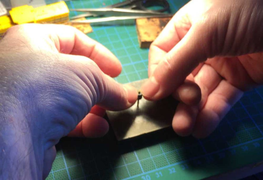
Wenn fitting the supplied brass adapters, please note that the worm has two sides: One FLAT side, one ANGLED side. Push the adapter in the FLAT side and push it completely though until it reaches the other side of the adapter. You do this, as this is easier. The angled side is tighter.
Make sure the motor contacts are pushed outwards, so they rest flat on the motor.
Fit the flywheel with the open side outwards on the longest brass adapter. Press it as close to the contacts as possible, without making contact. Wiggle the motor shaft back and forth to check.
6
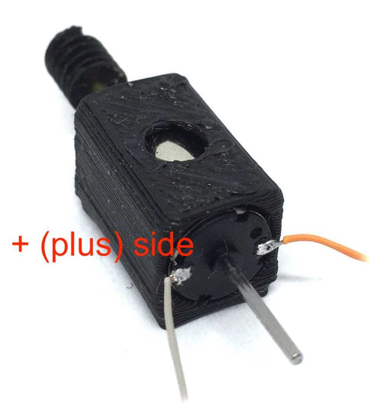
Don’t let the colours of the wires confuse you. The left side is the plus side. You can see a little plus next to the contact.
8
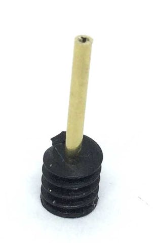
Fit the worms. If the friction of the fitting is too loose, use Loctite or similar products to glue them in place. Don’t use super glue, as the adapter will get stuck before you manage to get it in the correct position.
9
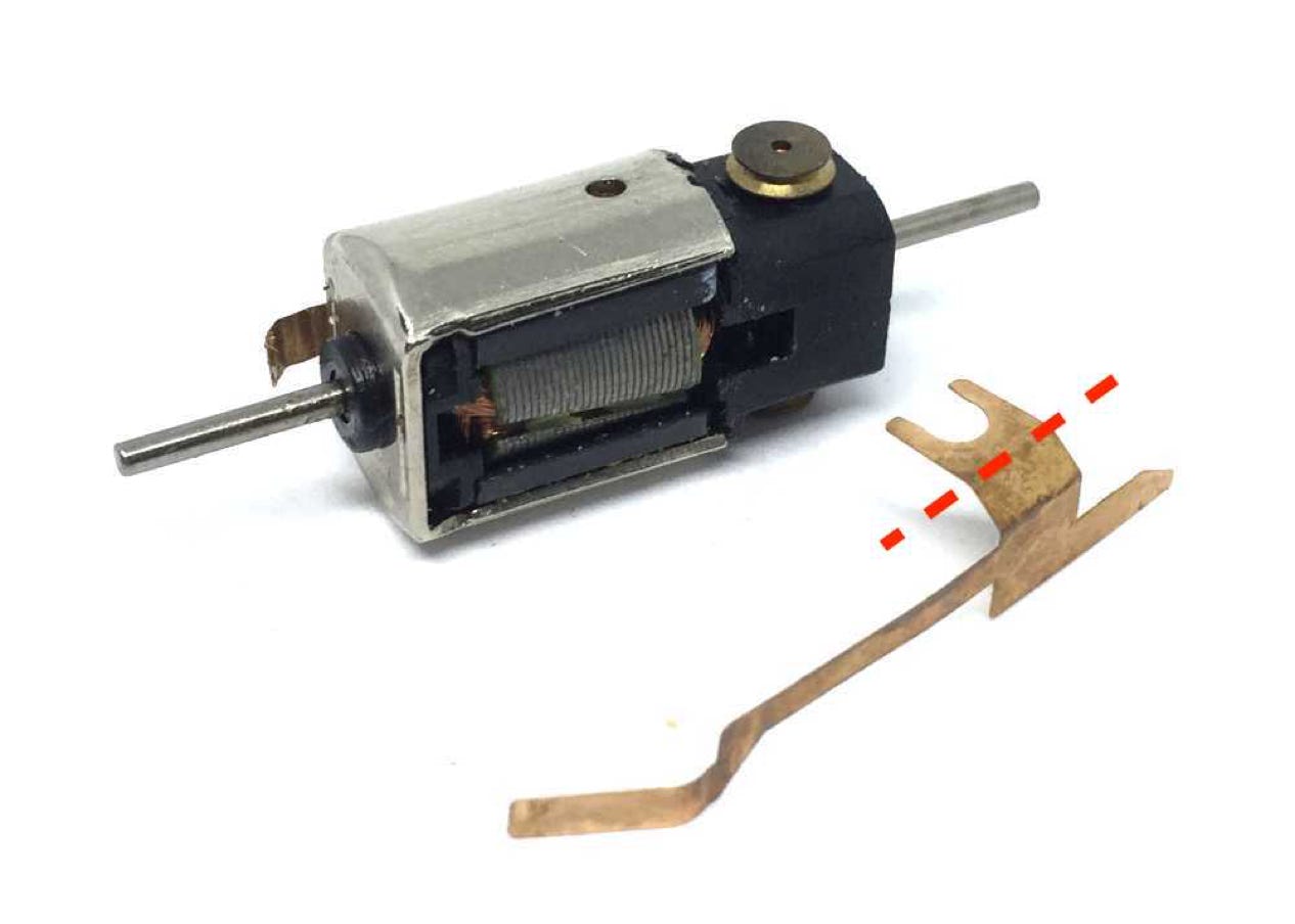
Cut both contact strips at around the space indicated and flatten them.
10
Solder the Plus wire to the contact strip, so it’s on the inside.
11
This side will be fitted around the motor assembly, so the ends touch the metal blocks.
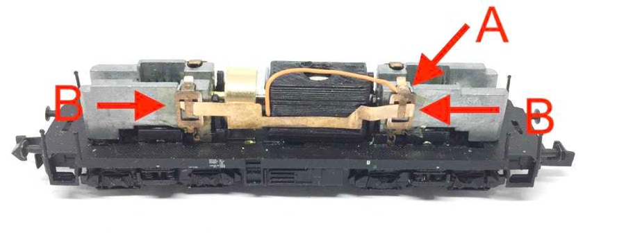
12
The cable on the other side will be fitted under the contact strip, as seen on the image (A). Makes sure it DOES NOT TOUCH the metal block. The connector inside the metal block is insulated from the metal block, so the wire to the motor should go directly on this single point. But, you can also just solder it to the contact strip. Make sure the tape between the contact strip and metal block on both sides is still in place (B).
13
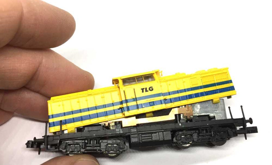
After testing the model on the track, close the housing in an angle. Check if the contact strips don’t slide out of place.
Digital
If it all works well, you can fit a decoder. Train-O-Matic makes excellent small decoder, available here from the Tramfabriek.
For optimal performance, you need to change some CV settings on a decoder. For several decoder brands, the ideal CV settings can be found by clicking here.
END
•